


TROUBLESHOOTING & REPAIR
F-51 F-51
RANGER 250
Return to Section TOC Return to Section TOC Return to Section TOC Return to Section TOC
Return to Master TOC Return to Master TOC Return to Master TOC Return to Master TOC
POWER MODULE ASSEMBLY
REMOVAL AND REPLACEMENT
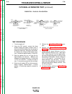
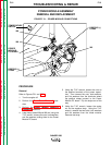
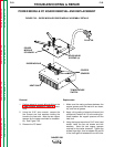
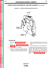
FIGURE F. 21 – POWER MODULE CONNECTIONS
POSITIVE (+)
STRAP
W6
W9
POWER
MODULE
PC BOARD
TEMPERATURE
SWITCH
POSITIVE (+)
STRAP
W8
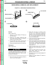
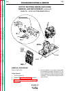
PROCEDURE
Removal
Refer to Figures F.21 and F.22.
1. Turn the engine off.
2. Perform the Case Cover Removal proce-
dure.
3. Perform the Power Module Capacitor
Discharge procedure.
4. Label heavy leads W8 and W9 and, using the
7/16" wrench, remove the nuts, lock washers,
and flat washers holding them to the Power
Module PC board.
5. Using the 7/16" wrench, loosen the nuts on
the positive terminals of the power capaci-
tors. Then remove the nuts, lock washers,
and flat washers from the terminals where
the positive straps connect to the Power
Module PC board. Flip the straps out of the
way.
6. Using the 7/16" wrench, loosen the center
nut on the negative strap. Using the 7/16"
wrench, remove the two bolts, lock washers
and flat washers from the diode module.
Remove the strap.