


TROUBLESHOOTING & REPAIR
F-32 F-32
RANGER 250
Return to Section TOC Return to Section TOC Return to Section TOC Return to Section TOC
Return to Master TOC Return to Master TOC Return to Master TOC Return to Master TOC
STATOR VOLTAGE TESTS (continued)
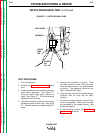
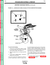
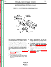
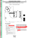
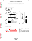
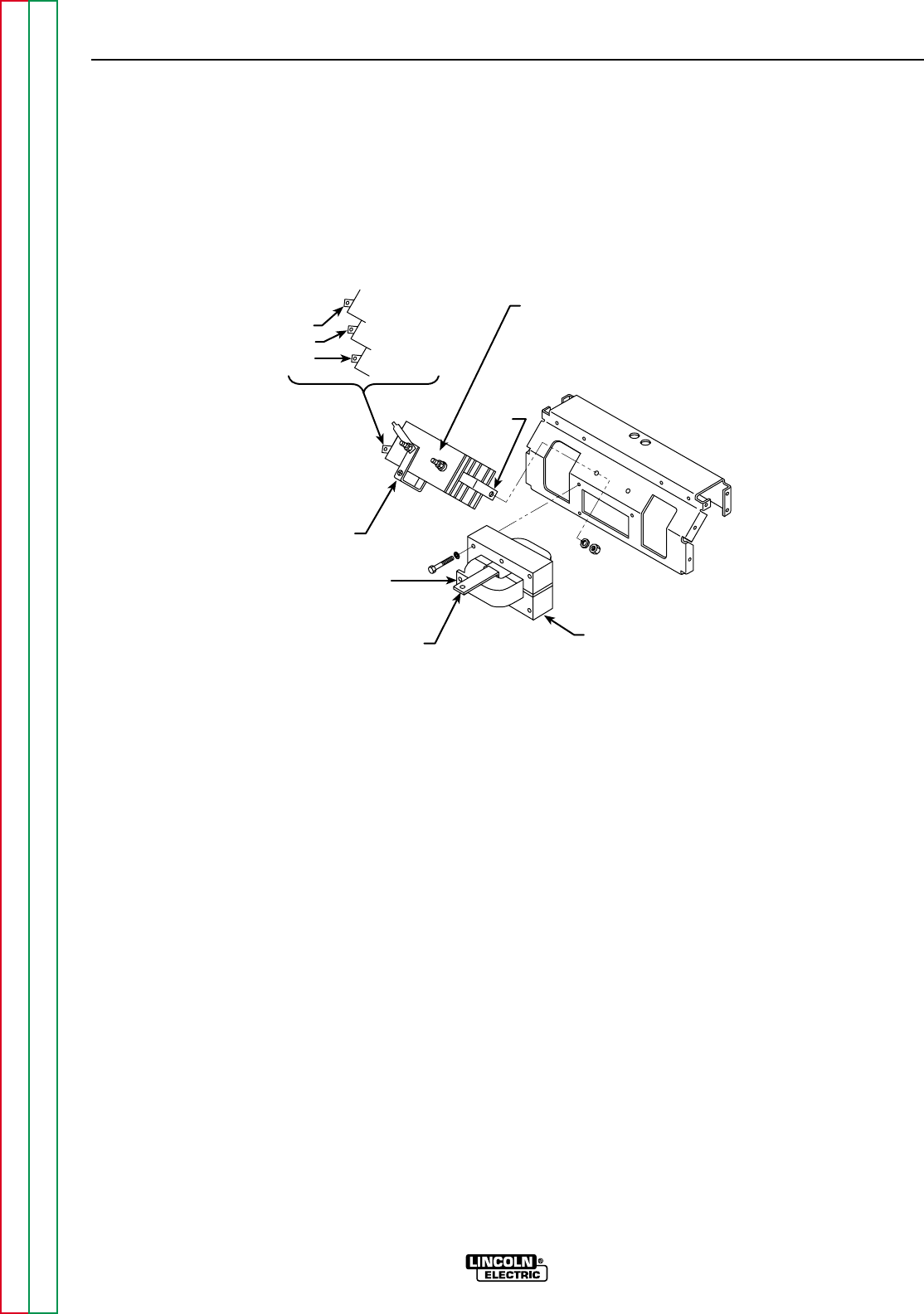
FIGURE F.13 – OUTPUT RECTIFIER BRIDGE CONNECTIONS
W1
W2
W3
W4
W5
W10
W8
W9
W6
W7
W11
OUTPUT
RECTIFIER
BRIDGE
TOP
CENTER
BOTTOM
CHOKE
If any one or more of the readings are missing or
not within specifications, then check for loose or
broken wires between the test points and the sta-
tor windings. See the Wiring Diagram. Make
sure that the windings are NOT grounded inter-
nally to the stator iron. If the leads are intact,
then the stator may be faulty. Replace the stator.
If the voltage readings are within specifications,
then the windings are good and functioning prop-
erly.
7. If finished testing, perform the Case Cover
Replacement procedure.
To test the stator weld windings:
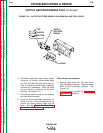
1. Locate the weld winding leads connected to
the three-phase output rectifier bridge. See
Figure F.13.
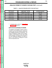
2. Check for approximately 58 - 65 VAC from
W1 to W2. Also check for the same voltage
from W2 to W3 and from W1 to W3.
3. If any of these voltages are low or missing,
perform the Flashing and Rotor Voltage
Test and also the Rotor Resistance Test.
4. If the tests in Step 2 are OK and the stator
voltages are low or missing, the stator may
be faulty.
5. If finished testing, perform the Case Cover
Replacement procedure.