


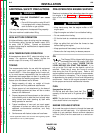

BATTERY CONNECTIONS
BATTERY ACID CAN BURN EYES AND
SKIN.
• Wear gloves and eye protection and be
careful when working near a battery.
Follow the instructions printed on the
battery.
Use caution as the electrolyte is a strong acid that can
burn skin and damage eyes.
The Ranger 250 is shipped with the negative battery
cable disconnected. Make certain that the RUN-STOP
switch is in the STOP position. Remove the screws
from the rear battery tray using a screwdriver or a 3/8"
socket. Attach the negative battery cable to the nega-
tive battery terminal and tighten using a socket or
wrench.
NOTE: This machine is furnished with a wet charged
battery; if unused for several months, the battery may
require a booster charge. Be careful to charge the bat-
tery with the correct polarity. See the battery charging
instructions in the Maintenance section.
MUFFLER OUTLET PIPE
Using the clamp provided, secure the outlet pipe to the
outlet tube with the pipe positioned to direct the ex-
haust in the desired direction. Tighten using a socket or
wrench.
SPARK ARRESTER
Some federal, state or local laws may require spark
arresters in locations where unarrested sparks may
present a fire hazard. The standard muffler included
with this welder does not qualify as a spark arrester.
When required by local regulations, a suitable spark
arrester, such as the S24647, must be installed and
properly maintained. See the Accessories section for
more information.
An incorrect spark arrester may lead to engine damage
or may adversely affect performance.
HIGH FREQUENCY GENERATORS FOR
TIG APPLICATIONS
The K930-2 TIG Module is suitable for use with the
Ranger 250. The Ranger 250 and any high frequency
generating equipment must be properly grounded.
See the K930-2 operating manual for complete instruc-
tions on installation, operation, and maintenance.
REMOTE CONTROL
The Ranger 250 is equipped with a 6-pin and a 14-pin
Amphenol connector. The 6-pin connector is for con-
necting the K857 or K857-1 Remote Control (optional)
or for TIG welding, the K870 foot Amptrol or the K963-
2 hand Amptrol.
When in the CC-STICK, PIPE, and CV-WIRE modes
and when a remote control is connected to the
Amphenol, the auto-sensing circuit in the Ranger 250
automatically switches the OUTPUT control from con-
trol at the welder to remote control.
The 14-pin connector is used to directly connect a wire
feeder. In the CV-WIRE mode, the Ranger 250 auto-
sensing circuit automatically makes the Ranger 250
OUTPUT control inactive and the wire feeder voltage
control active when the control cable is connected to
the 14-pin connector.
NOTE: When a wire feeder with a built in welding volt-
age control is connected to the 14-pin connector, do
NOT connect anything to the 6-pin connector.
WELDING TERMINALS
The Ranger 250 is equipped with a toggle switch for
selecting “hot” welding terminals when in the “WELD
TERMINALS ON” position or “cold” welding terminals
when in the “REMOTELY CONTROLLED” position.
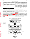
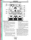
ELECTRICAL OUTPUT
CONNECTIONS
See Figure A.1 for the location of the 120 and 240 volt
receptacles, weld output terminals, and ground stud.
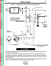
MACHINE GROUNDING
Because this portable engine driven welder
creates its own power, it is not necessary to connect its
frame to an earth ground, unless the machine is con-
nected to premises wiring (home, shop, etc.)
INSTALLATION
A-5 A-5
RANGER 250
Return to Section TOC Return to Section TOC Return to Section TOC Return to Section TOC
Return to Master TOC Return to Master TOC Return to Master TOC Return to Master TOC
WARNING
CAUTION