


Return to Section TOC Return to Section TOC Return to Section TOC Return to Section TOC
Return to Master TOC Return to Master TOC Return to Master TOC Return to Master TOC
TROUBLESHOOTING & REPAIR
F-4 F-4
RANGER 250
If for any reason you do not understand the test procedures or are unable to perform the test/repairs safely,
contact the Lincoln Electric Service Department for electrical troubleshooting assistance before you proceed. Call
1-800-833-9353.
PROBLEMS
(SYMPTOMS)
POSSIBLE AREAS OF
MISADJUSTMENT(S)
RECOMMENDED
COURSE OF ACTION
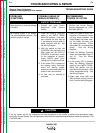
OUTPUT PROBLEMS
Major physical or electrical damage
is evident.
1. Contact your local Lincoln
Authorized Field Service
Facility.
1. Contact the Lincoln Electric
Service Department at 1-800-
833-9353 (WELD).
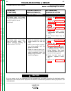
No welding output in all modes.
The engine operates normally. The
auxiliary output is normal.
1. Place the Welding Terminals
switch in the “WELD TERMI-
NALS ON” position. If the prob-
lem is solved, the fault may be
in the external control cable (if
used), leads #2 and #4. See
the Wiring Diagram.
2. With the engine at high idle
(3700RPM), the machine in the
Stick mode and the OUTPUT
CONTROL at maximum, check
for the presence of approxi-
mately 80VDC (open circuit
voltage) at the output terminals.
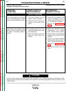
3. If the correct OCV is present at
the welding output terminals,
check the welding cables,
clamps and electrode holder for
loose or faulty connections.
4. Air flow may be blocked or
restricted.
1. Check for loose or faulty con-
nections on the heavy current
carrying leads between the
output bridge, the power mod-
ule, the choke, the shunt and
the output terminals. Check
thermostat TS1 and associated
wiring. See the Wiring
Diagram.
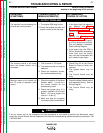
2. Check the Welding Terminals
switch and associated leads (2
and 4). See the Wiring
Diagram.
3. If the correct OCV is present
when the Welding Terminals
switch is in the “WELD TERMI-
NALS ON” position, the By-
pass Board may be faulty. Also
check associated wiring. See
the Wiring Diagram.
4. Check gate leads (#23 and
#25) for loose or faulty connec-
tions. See the Wiring Diagram.
CAUTION
Observe Safety Guidelines
detailed in the beginning of this manual.
TROUBLESHOOTING GUIDE