


STICK WELDING
The Ranger 250 can be used with a broad range of DC
stick electrodes.
The MODE switch provides two stick welding settings
as follows:
CONSTANT CURRENT (CC-STICK) WELDING
The CC-STICK position of the MODE switch is
designed for horizontal and vertical-up welding with all
types of electrodes, especially low hydrogen. The
OUTPUT control adjusts the full output range for stick
welding.
The ARC control sets the short circuit current during
stick welding (arc-force). Increasing the number from
-10 to +10 increases the short circuit current and pre-
vents sticking of the electrode to the plate while weld-
ing. This can also increase spatter. It is recommended
that the ARC control be set to the minimum number
without electrode sticking. Start with the dial set at 0.
PIPE WELDING
This slope-controlled setting is intended for “out-of-
position” and “downhill” pipe welding where the opera-
tor would like to control the current level by changing
the arc length. The OUTPUT control dial adjusts the full
output range for pipe welding. The ARC control is not
active in the PIPE mode.
OPERATION
B-8 B-8
RANGER 250
Return to Section TOC Return to Section TOC Return to Section TOC Return to Section TOC
Return to Master TOC Return to Master TOC Return to Master TOC Return to Master TOC
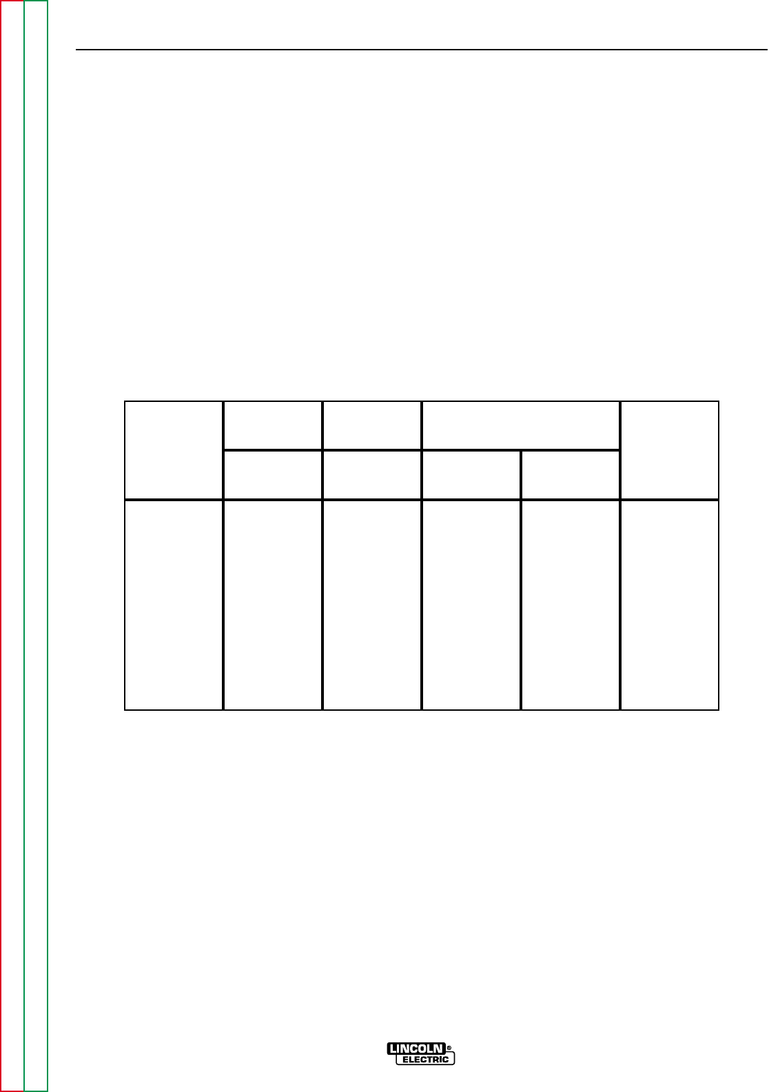
Tungsten
Electrode
Diameter
in. (mm)
2-15
5-20
15-80
70-150
150-250
250-400
400-500
500-750
750-1000
3
3
3
10-20
15-30
25-40
40-55
55-80
180-125
3-8 (2-4)
5-10 (3-5)
5-10 (3-5)
5-10 (3-5)
13-17 (6-8)
15-23 (7-11)
21-25 (10-12)
23-27 (11-13)
28-32 (13-15)
3-8 (2-4)
5-10 (3-5)
5-10 (3-5)
9-13 (4-6)
11-15 (5-7)
11-15 (5-7)
13-17 (6-8)
18-22 (8-10)
23-27 (11-13)
TIG TORCH
Nozzle
Size
4, 5
Approximate Argon Gas Flow Rate
C.F.H. (l/min.)
DCEN (-) DCEP (+)
#4, #5, #6
#5, #6
#6, #7, #8
#8, #10
0 .010 (.25)
0.020 (.50)
0.040 (1.0)
1/16 (1.6)
3/32 (2.4)
1/8 (3.2)
5/32 (4.0)
3/16 (4.8)
1/4 (6.4)
1%, 2%
Thoriated
Tungsten
1%, 2%
Thoriated
Tungsten
Aluminum Stainless Steel
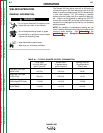
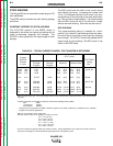
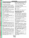
TABLE B.2 – TYPICAL CURRENT RANGES
1
FOR TUNGSTEN ELECTRODES
2
1
When used with argon gas. The current ranges shown must be reduced when using argon/helium or pure helium shield-
ing gases.
2
Tungsten electrodes are classified as follows by the American Welding Society (AWS):
Pure EWP
1% Thoriated EWTh-1
2% Thoriated EWTh-2
Though not yet recognized by the AWS, Ceriated Tungsten is now widely accepted as a substitute for 2% Thoriated
Tungsten in AC and DC applications.
3
DCEP is not commonly used in these sizes.
4
TIG torch nozzle “sizes” are in multiples of 1/16ths of an inch:
# 4 = 1/4 in. (6 mm)
# 5 = 5/16 in. (8 mm)
# 6 = 3/8 in. (10 mm)
# 7 = 7/16 in. (11 mm)
# 8 = 1/2 in. (12.5 mm)
#10 = 5/8 in. (16 mm)
5
TIG torch nozzles are typically made from alumina ceramic. Special applications may require lava nozzles, which are
less prone to breakage, but cannot withstand high temperatures and high duty cycles.