


Return to Section TOC Return to Section TOC Return to Section TOC Return to Section TOC
Return to Master TOC Return to Master TOC Return to Master TOC Return to Master TOC
TROUBLESHOOTING & REPAIR
F-18 F-18
RANGER 250
IDLER SOLENOID TEST (continued)
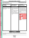
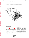
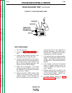
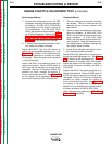
FIGURE F.3 – IDLER SOLENOID LEADS
SOLENOID
HOUSING
STATOR
LEADS #210C
AND #215 TO
CONNECTORS
TEST PROCEDURE
1. Turn the engine off.
2. Perform the Case Cover Removal proce-
dure.
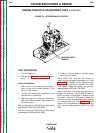
3. Locate the idler solenoid mounted on the
stator beside the fuel tank filler neck.
4. Locate and remove the two in-line connec-
tors that attach the idler solenoid leads to
the wiring harness leads (#210C and
#215). Cut any necessary cable ties. See
Figure F.3 and the Wiring Diagram.
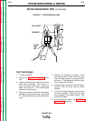
5. Check the coil resistance. The normal
resistance is approximately 15 ohms. If the
coil resistance is not correct, the solenoid
may be faulty. Replace.
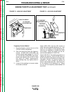
6. Using the external 12VDC supply, apply
12VDC to the solenoid leads. Push the
solenoid plunger in (this simulates the
action that takes place when the engine is
running and there is less resistance to
solenoid movement) and check that it
holds by itself. The solenoid should deac-
tivate when the 12VDC is removed.
7. If the solenoid does not operate properly,
check for a mechanical restriction in the
linkage. Also check for proper operation
of the governor. See the Engine Owner's
Manual.
8. If the linkage is intact and the solenoid
does not operate correctly when the
12VDC is applied, the solenoid may be
faulty. Replace.
9. Replace leads #210C and #215 to the
correct in-line connectors. See Figure F.3
and the Wiring Diagram. Replace any
previously removed cable ties.
10. If finished testing, perform the Case
Cover Replacement procedure.