


Return to Section TOC Return to Section TOC Return to Section TOC Return to Section TOC
Return to Master TOC Return to Master TOC Return to Master TOC Return to Master TOC
TROUBLESHOOTING & REPAIR
F-27 F-27
RANGER 250
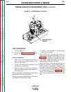
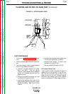
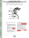
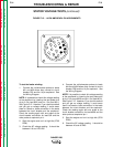
FIGURE F.9 – FIELD DIODE RECTIFIER BRIDGE AND FILTER CAPACITOR
FIELD
RECTIFIER
BRIDGE
RETAINING
TAB
7
9
CAPACITOR
201
201A
200A
200B
CABLE
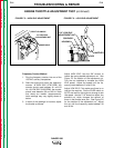
FLASHING AND ROTOR VOLTAGE TEST (continued)
4. Test rotor voltage - dynamic (engine run-
ning)
a. Remove the jumper used in the previous
step. Replace the spark plug wires, set
the RUN/STOP switch to RUN, start the
engine and run it at high idle speed
(3700 RPM).
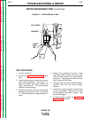
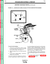
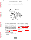
b. Connect the positive meter probe to the
brush nearest the rotor lamination (leads
#200A and #200). See Figure F.8 for
location.
c. Connect the negative meter probe to the
other brush (leads #201 and #5H).
d. Carefully measure the voltage. It should
read approximately 46 - 52 VDC.
5. If the voltage reading is low or not present,
the generator field is not functioning prop-
erly. Perform the Rotor Resistance Test.
Also check the field diode rectifier bridge,
filter capacitor, and associated leads and
connections. See Figure F.9 for location.
See the Wiring Diagram.
6. Check the rotor ground wire #5H for good
connection. See the Wiring Diagram.
7. If the rotor voltage readings are normal, the
field circuit is functioning properly.
8. If finished testing, perform the Case Cover
Replacement procedure.