


Return to Section TOC Return to Section TOC Return to Section TOC Return to Section TOC
Return to Master TOC Return to Master TOC Return to Master TOC Return to Master TOC
TROUBLESHOOTING & REPAIR
F-30 F-30
RANGER 250
STATOR VOLTAGE TESTS (continued)
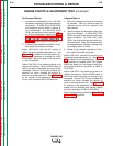
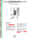
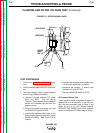
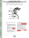
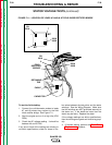
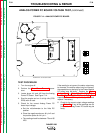
FIGURE F.11 – LOCATION OF LEADS #7 AND #9 AT FIELD DIODE RECTIFIER BRIDGE
FIELD
RECTIFIER
BRIDGE
RETAINING
TAB
7
9
CAPACITOR
201
201A
200A
200B
CABLE
201
201A
200A
200B
7
9
+
_
AC
AC
To test the field winding:
1. Connect the volt/ohmmeter probes to leads
#7 and #9 where they connect to the field
diode rectifier bridge. See Figure F.11.
2. Start the engine and run it at high idle (3700
RPM).
3. Check the AC voltage reading. It should be
between 40 and 50 VAC.
If any one or more of the readings are missing or
not within specifications, check for loose or bro-
ken wires between the test points and the stator
windings. See the Wiring Diagram. Make sure
that the windings are NOT grounded internally to
the stator iron. If the leads are intact, then the
stator may be faulty. Replace the stator.
If the voltage readings are within specifications,
then the windings are good and functioning prop-
erly.
4. If finished testing, perform the Case Cover
Replacement procedure.