


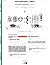
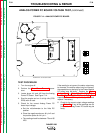
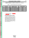
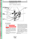

TABLE F.1. – ANALOG PC BOARD OUTPUT VOLTAGE TABLE
TEST POINTS COMPONENT TESTED VOLTAGE READING
1J42 to 6J42 Chopper Power Supply +20 VDC
2J42 to 7J42 Weld Control PC Board Power Supply +5 VDC
5J42 to 7J42 Weld Control PC Board Power Supply +15 VDC
9J42 to 7J42 Weld Control PC Board Power Supply -15 VDC
10J42 to 4J42 Weld Control PC Board Power Supply +15 VDC
TROUBLESHOOTING & REPAIR
F-35 F-35
RANGER 250
Return to Section TOC Return to Section TOC Return to Section TOC Return to Section TOC
Return to Master TOC Return to Master TOC Return to Master TOC Return to Master TOC
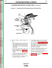
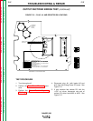
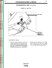
ANALOG POWER PC BOARD VOLTAGE TEST (continued)
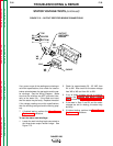
7. If finished testing, perform the Case Cover
Replacement procedure.
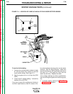
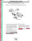
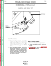
NOTE ON THE BYPASS PC BOARD
The purpose of the Bypass PC board circuitry is
to provide a more attractive path to ground for
transient spikes and high frequency signals that
could damage sensitive circuit components. The
Ranger 250 Bypass PC board cannot be tested.
However, a faulty Bypass PC may show visible
physical damage. As a general rule of practice, if
you have catastrophic damage to any other PC
board on the machine, the Bypass PC board
should be replaced as well.