


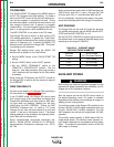
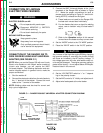
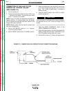
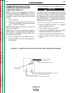
CONNECTION OF THE LN-25 TO THE
RANGER 250 “ACROSS THE ARC”
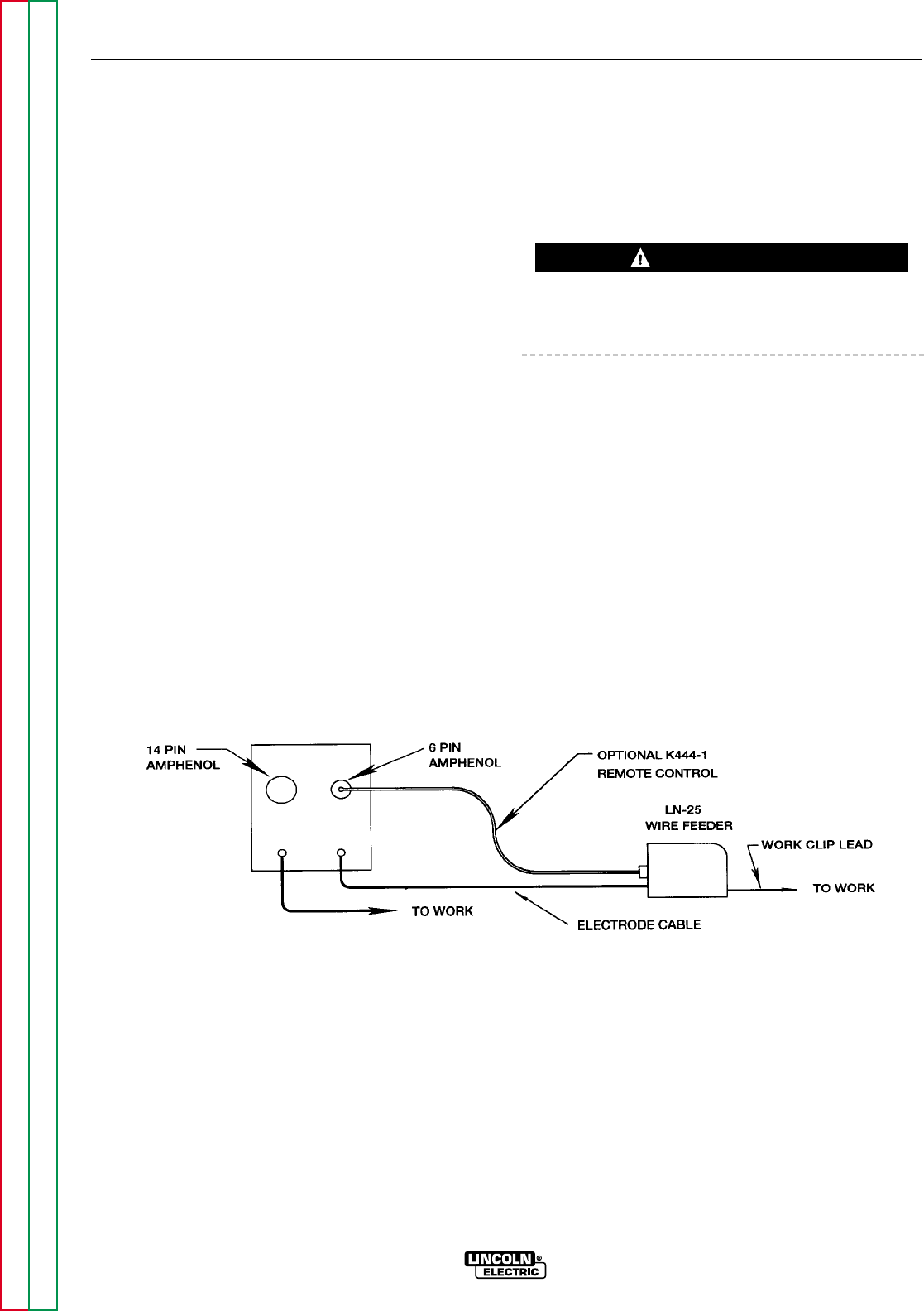
(SEE FIGURE C.2.)
1. Shut the welder off.
2. Connect the electrode cable from the LN-25 to the
“-” terminal of the welder. Connect the work cable
to the “+” terminal of the welder.
NOTE: Figure C.2 shows the electrode connected for
negative polarity. To change polarity, shut the welder
off and reverse the electrode and work cables at the
Ranger 250 output terminals.
NOTE: Welding cable must be sized for current and
duty cycle of application.
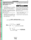
3. Set the “VOLTMETER” switch to “+” or “-” depend-
ing on the polarity chosen.
4. Set the “MODE” switch to the “CV-WIRE” position.
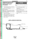
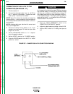
5. Attach the single lead from the LN-25 control box
to the work using the spring clip on the end of the
lead. This is only a control lead – it carries no
welding current.
6. Place the “IDLER” switch in the “AUTO” or “HIGH”
position as desired.
If you are using an LN-25 without an internal contactor,
the electrode will be “HOT” when the Ranger 250 is
started.
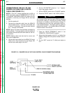
7. Place the “WELD TERMINALS” switch in the
“WELD TERMINALS ON” position.
8. Adjust wire feed speed at the LN-25 and adjust the
welding voltage with the output “CONTROL” at the
LN-25 if optional remote control kit is used.
9. Set the ARC control to “0” initially and adjust to suit.
ACCESSORIES
C-4 C-4
RANGER 250
Return to Section TOC Return to Section TOC Return to Section TOC Return to Section TOC
Return to Master TOC Return to Master TOC Return to Master TOC Return to Master TOC
CAUTION
FIGURE C.2 – RANGER 250/LN-25 ACROSS THE ARC CONNECTION DIAGRAM
-
-
+ –