


To prevent dangerous electric shock, other equipment
to which this engine driven welder supplies power
must:
a) Be grounded to the frame of the welder using a
grounded type plug.
b) Be double insulated.
Do not ground the machine to a pipe that carries explo-
sive or combustible material.
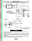
When this welder is mounted on a truck or trailer, its
frame must be securely connected to the metal frame
of the vehicle. When connected to premises wiring
such as that in a home or shop, the welder frame must
be connected to the system earth ground. See further
connection instructions in the section entitled Standby
Power Connections as well as the article on ground-
ing in the latest U.S. National Electrical Code and the
local code.
In general, if the machine is to be grounded, it should
be connected with a #8 or larger copper wire to a solid
earth ground such as a metal water pipe going into the
ground for at least ten feet and having no insulated
joints, or to the metal framework of a building which
has been effectively grounded. The U.S. National
Electrical Code lists a number of alternate means of
grounding electrical equipment. A machine grounding
stud marked with the ground symbol is provided
on the front of the welder.
WELDING OUTPUT CABLES
With the engine off, connect the electrode and work
cables to the output terminals. The welding process
dictates the polarity of the electrode cable. These con-
nections should be checked periodically and tightened
with a wrench.
Table A.1 lists recommended cable sizes and lengths
for rated current and duty cycle. Length refers to the
distance from the welder to the work and back to the
welder. Cable diameters are increased for long cable
lengths to reduce voltage drops. Avoid coiling long
cables on the machine when welding.
INSTALLATION
A-6 A-6
RANGER 250
Return to Section TOC Return to Section TOC Return to Section TOC Return to Section TOC
Return to Master TOC Return to Master TOC Return to Master TOC Return to Master TOC
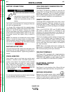
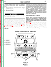
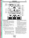
FIGURE A.1 – RANGER 250 OUTPUT CONNECTIONS
CHOKE
RUN
START HIGH
IDLER
AUTO
G3668 VM
STOP
K NO.- CODE - SERIAL NO.
OUTPUT
20 CV
120 CC
22 CV
155 CC
24 CV
190 CC
17 CV
85 CC
26 CV
220 CC
28 CV
250 CC
14 CV
50 CC
12 CV
20 CC
THE LINCOLN ELECTRIC COMPANY CLEVELAND, OHIO USA
CV-WIRE
ARC CONTROL
WELD MODE
PIPE
CC-STICK
TOUCH START TIG
SOFT CRISP
+8
+6
+4
+2
0
-2
-4
-6
-8
-10
+10
WELD
TERMINALS ON
WIRE FEEDER
VOLTMETER
REMOTELY
CONTROLLED
NRTL/C
CIRCUIT
BREAKERS
120/240 V
120 V
WELDER OUTPUT RATING
VOLTS
DUTY CYCLE
250 DC 100% 25
80V MAX OCV AT RATED 3700 RPM
AMPS
AUXILIARY POWER RATING
VOLTS
DUTY CYCLE
WATTS
8,000
100% 120/240
AVAILABLE POWER IS REDUCED WHILE WELDING
SINGLE PHASE 60 HZ
SIMULTANEOUS WELDING AND POWER
WELD CURRENT
AMPS
AUX. POWER
WATTS
240 V.RECEPTACLE
AMPS
0
100
150
200
250
8000
5000
3000
1500
0
33
21
13
6
0
NEUTRAL GROUND TO FRAME
Hobbs
QUARTZ
HOURS
0 0 0 0 0 0
1
2
4
3
1. 120 VAC
RECEPTACLES
2. 120/240 VAC
RECEPTACLES
3. WELD OUTPUT
TERMINALS
4. GROUND STUD
WARNING