


Return to Master TOC Return to Master TOC Return to Master TOC Return to Master TOC
Section F-1 Section F-1
RANGER 250
Troubleshooting & Repair Section ................................................................................Section F
How to Use Troubleshooting Guide.......................................................................................F-2
PC Board Troubleshooting Procedures .................................................................................F-3
Troubleshooting Guide................................................................................................F-4 - F-12
Test Procedures...................................................................................................................F-13
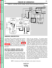
Case Cover Removal and Replacement Procedure ....................................................F-13
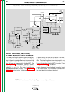
Power Module Capacitor Discharge Procedure ...........................................................F-15
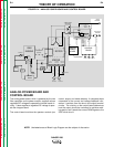
Idler Solenoid Test ........................................................................................................F-17
Engine Throttle Adjustment Test ...................................................................................F-19
Rotor Resistance Test ..................................................................................................F-23
Flashing and Rotor Voltage Test ..................................................................................F-25
Stator Voltage Tests .....................................................................................................F-28
Analog Power PC Board Voltage Test .........................................................................F-33
Output Rectifier Bridge Test .........................................................................................F-36
Power Module Test .......................................................................................................F-39
Flywheel Alternator Test ................................................................................................F-43
Oscilloscope Waveforms......................................................................................................F-45
Normal Open Circuit Voltage Waveform (120 VAC Supply)..........................................F-45
Normal Open Circuit Voltage Waveform (Stick) ............................................................F-46
Normal Weld Voltage Waveform (Stick CC)..................................................................F-47
Normal Open Circuit Voltage Waveform (Wire CV Tap)................................................F-48
Normal Weld Voltage Waveform (Wire CV) ..................................................................F-49
Replacement Procedures ....................................................................................................F-50
Power Module Assembly/Power Module PC Board/
Diode Module Removal and Replacement....................................................................F-50
Power Capacitor Removal and Replacement ...............................................................F-55
Output Rectifier Bridge and Choke Removal and Replacement...................................F-57
Engine/Stator/Rotor Removal and Replacement ..........................................................F-60
Retest After Repair...............................................................................................................F-68
TABLE OF CONTENTS
TROUBLESHOOTING & REPAIR SECTION