


Return to Section TOC Return to Section TOC Return to Section TOC Return to Section TOC
Return to Master TOC Return to Master TOC Return to Master TOC Return to Master TOC
OPERATION
B-4 B-4
RANGER 250
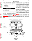
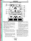
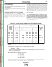
ENGINE CONTROLS
1. RUN/STOP SWITCH: RUN position energizes the
engine prior to starting. STOP position stops the
engine. The oil pressure interlock switch prevents
battery drain if the switch is left in the RUN position
and the engine is not operating.
2. CHOKE: When pulled out, it closes the choke valve
on the engine carburetor for quick starting.
3. START PUSHBUTTON: Energizes the starter
motor to crank the engine.
4. IDLER SWITCH: Has two positions as follows:
A) In the HIGH position, the engine runs at the high
idle speed controlled by the engine governor.
B) In the AUTO position, the idler operates as fol-
lows:
a. When switched from HIGH to AUTO or after
starting the engine, the engine will operate
at high speed for approximately 12 seconds
and then go to low idle speed.
b. When the electrode touches the work or
power is drawn from the auxiliary power
receptacles (approximately 100 watts mini-
mum), the engine accelerates and operates
at high speed.
c. When welding ceases or the AC power load
is turned off, a fixed time delay of approxi-
mately 12 seconds starts. If the welding or
AC power load is not restarted before the
end of the time delay, the idler reduces the
engine speed to low idle speed.
d. The engine will automatically return to high
idle speed when the welding load or AC
power load is reapplied.
5. ENGINE ALTERNATOR TROUBLE LIGHT: The
yellow engine alternator light is off when the battery
charging system is functioning normally. If the light
turns on, the alternator or the voltage regulator may
not be operating correctly. The light may also come
on if the battery is not holding a charge. It is normal
for the light to come on while starting the engine.
6. ENGINE HOUR METER: Displays the total time
that the engine has been running. This meter is
useful for scheduling prescribed maintenance.
FIGURE B.1 – CASE FRONT PANEL CONTROLS
CHOKE
RUN
START HIGH
IDLER
AUTO
G3668 VM
STOP
K NO.- CODE - SERIAL NO.
OUTPUT
20 CV
120 CC
22 CV
155 CC
24 CV
190 CC
17 CV
85 CC
26 CV
220 CC
28 CV
250 CC
14 CV
50 CC
12 CV
20 CC
THE LINCOLN ELECTRIC COMPANY CLEVELAND, OHIO USA
CV-WIRE
ARC CONTROL
WELD MODE
PIPE
CC-STICK
TOUCH START TIG
SOFT CRISP
+8
+6
+4
+2
0
-2
-4
-6
-8
-10
+10
WELD
TERMINALS ON
WIRE FEEDER
VOLTMETER
REMOTELY
CONTROLLED
NRTL/C
CIRCUIT
BREAKERS
120/240 V
120 V
WELDER OUTPUT RATING
VOLTS
DUTY CYCLE
250 DC 100% 25
80V MAX OCV AT RATED 3700 RPM
AMPS
AUXILIARY POWER RATING
VOLTS
DUTY CYCLE
WATTS
8,000
100% 120/240
AVAILABLE POWER IS REDUCED WHILE WELDING
SINGLE PHASE 60 HZ
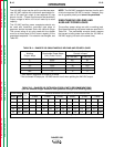
SIMULTANEOUS WELDING AND POWER
WELD CURRENT
AMPS
AUX. POWER
WATTS
240 V.RECEPTACLE
AMPS
0
100
150
200
250
8000
5000
3000
1500
0
33
21
13
6
0
NEUTRAL GROUND TO FRAME
Hobbs
QUARTZ
HOURS
0 0 0 0 0 0
10
11
12
13
5
2
3
4
6
1
7
9
8