


Return to Section TOC Return to Section TOC Return to Section TOC Return to Section TOC
Return to Master TOC Return to Master TOC Return to Master TOC Return to Master TOC
TROUBLESHOOTING & REPAIR
F-26 F-26
RANGER 250
FLASHING AND ROTOR VOLTAGE TEST (continued)
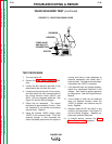
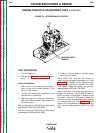
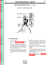
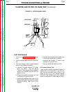
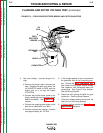
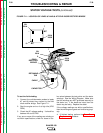
FIGURE F.8 – ROTOR BRUSH LEADS
SLIP RINGS
BRUSHES
LEADS
201
5H
+
-
LEADS
200A
200
TEST PROCEDURE
1. Perform the Case Cover Removal proce-
dure.
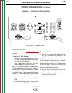
2. Set the volt/ohmmeter to the DC volts posi-
tion.
3. Test rotor voltage - static (engine stopped
but running condition simulated):
a. Connect a jumper between P51 leads
#210 and #224. See the Wiring
Diagram. This bypasses the oil pressure
switch and simulates the test with the
engine running.
b. Remove the spark plug wires, then set
the RUN/STOP switch to RUN.
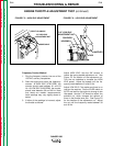
c. Connect the positive meter probe to the
brush nearest the rotor lamination (leads
#200A and #200). See Figure F.8 for
location.
d. Connect the negative meter probe to the
other brush (leads #201 and #5H).
e. Measure the voltage. It should read
between 3.0 and 4.0 VDC.
f. Set the RUN/STOP switch to STOP.
Oil Pressure Switch Test
The oil pressure switch is designed to open if it
detects low or no oil pressure. If you can con-
duct the test described here in Step 3 and
obtain the 3.0 to 4.0 VDC voltage reading,
WITHOUT THE JUMPER, then the oil pressure
switch or the Battery PC board may be faulty.