


TROUBLESHOOTING & REPAIR
F-38 F-38
RANGER 250
Return to Section TOC Return to Section TOC Return to Section TOC Return to Section TOC
Return to Master TOC Return to Master TOC Return to Master TOC Return to Master TOC
OUTPUT RECTIFIER BRIDGE TEST (continued)
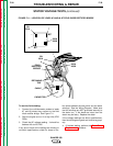
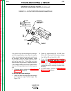
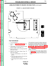
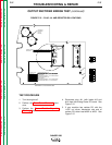
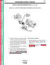
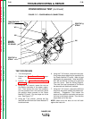
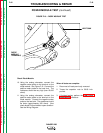
FIGURE F.16 – OUTPUT RECTIFIER BRIDGE LEAD REMOVAL AND TEST POINTS
W1
W2
W3
OUTPUT
RECTIFIER
BRIDGE
TOP
CENTER
BOTTOM
CHOKE
6. Electrically isolate the output rectifier bridge:
Using the 1/2" wrench, remove stator leads
W1, W2, and W3 from their bolted connec-
tions on the left side of the bridge. Note lead
placement for reassembly. Bend the leads
out into "free air" so that they do not touch
anything. See Figure F.16.
7. Remove any load that may be connected to
the weld output terminals.
8. Check all diode assemblies individually for
opens or shorts. If any of the checks are not
correct, the output rectifier bridge may be
faulty. See the Output Rectifier Bridge
Removal and Replacement procedure.
When all tests are complete:
1. Replace stator leads W1, W2, and W3 to
their respective terminals. Replace lead(s)
#252 or #253 previously removed. See
Figure F.16.
2. If finished testing, perform the Case Cover
Replacement procedure.