


TROUBLESHOOTING & REPAIR
F-53 F-53
RANGER 250
Return to Section TOC Return to Section TOC Return to Section TOC Return to Section TOC
Return to Master TOC Return to Master TOC Return to Master TOC Return to Master TOC
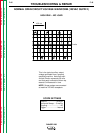
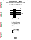
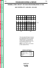
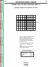
POWER MODULE PC BOARD REMOVAL AND REPLACEMENT
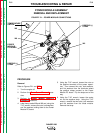
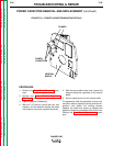
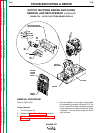
FIGURE F.22 – DIODE MODULE/POWER MODULE ASSEMBLY DETAILS
PLUG J50
ALLEN HEAD
SCREWS (4)
COPPER
SPACERS
TEMPERATURE
SWITCH
HEAT SINK
POWER
MODULE
PC BOARD
DIODE MODULE
Removal
1. Perform steps #1 through #6 and #8 from the
Power Module Assembly Removal proce-
dure.
2. Using the 3/16" allen wrench, remove the
four screws and lock washers holding the
board to the heat sink. Note the two copper
spacers for the center terminals for reassam-
bly. See Figure F.22.
3. Remove the PC board.
Replacement
1. Make sure the mating surfaces between the
copper spacers and the heat sink are clean,
dry, and free of grease.
2. Apply a thin coating of electrical thermal joint
compound (Penetrox A-13) to the mating sur-
faces between the copper spacers and the
heat sink.
3. Using the torque wrench and 3/16" allen head
socket, install the four set screws and lock
washers. Note the two copper spacers
required for the center terminals. Tighten the
screws finger tight, then to between 24 and 28
in-lbs, then again to between 40 and 48 in-lbs.