


Return to Section TOC Return to Section TOC Return to Section TOC Return to Section TOC
Return to Master TOC Return to Master TOC Return to Master TOC Return to Master TOC
TROUBLESHOOTING & REPAIR
F-22 F-22
RANGER 250
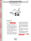
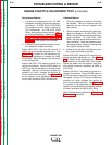
ENGINE THROTTLE ADJUSTMENT TEST (continued)
Oscilloscope Method
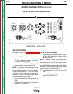
1. Connect the oscilloscope to the 120 VAC
receptacle, according to the manufacturer's
instructions. At HIGH IDLE (3700 RPM),
the waveform should exhibit a period of
16.2 milliseconds. At LOW IDLE (2400
RPM), the waveform should exhibit a peri-
od of 25.0 milliseconds. Refer to the NOR-
MAL OPEN CIRCUIT VOLTAGE WAVE-
FORM (120 VAC SUPPLY) HIGH IDLE -
NO LOAD in this section of the manual.
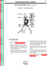
2. If either of these waveform periods is incor-
rect, adjust the throttle as follows:
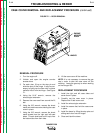
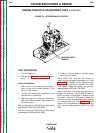
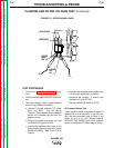
Adjust HIGH IDLE: Use the 3/8" wrench to
loosen the spring-loaded adjustment nut. See
Figure F.5 for location of the adjustment nut.
Turn the nut clockwise to increase the HIGH
IDLE speed. Adjust the speed until the period
is 16.2 milliseconds.
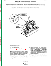
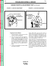
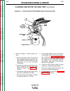
Adjust LOW IDLE: First make sure there is no
load on the machine. Set the IDLER switch to
AUTO and wait for the engine to change to low
idle speed. Use the 7/16" wrench to adjust the
solenoid nut, which changes the amount of
throw in the throttle lever arm. See Figure F.6
for the location of the adjustment nut. Adjust
the nut until the period is 25.0 milliseconds.
Vibratach Method
1. Place the vibratach as close to the engine
as possible. With the machine case top
removed, the top of the air cleaner is the
best location.
2. Start the engine and observe the whip han-
dle of the vibratach. At HIGH IDLE (3700
RPM), the whip handle should exhibit max-
imum oscillation. At LOW IDLE (2400
RPM), the whip handle should exhibit mini-
mum oscillation. Note that these are medi-
an measurements; vibratach readings may
vary slightly above or below.
3. If either of the vibratach indications is incor-
rect, adjust the throttle as follows:
Adjust HIGH IDLE: Use the 3/8" wrench to turn
the spring-loaded adjustment nut. See Figure
F.5 for location of the adjustment nut. Turn the
nut clockwise to increase HIGH IDLE speed.
Adjust the speed until the vibratach whip han-
dle exhibits maximum oscillation at 3650 to
3750 RPM.
Adjust LOW IDLE: First make sure there is no
load on the machine. Set the IDLER switch to
AUTO and wait for the engine to change to low
idle speed. Use the 7/16" wrench to adjust the
solenoid nut, which changes the amount of
throw in the throttle lever arm. See Figure F.6
for location of the adjustment nut. Adjust the
speed until the vibratach whip handle exhibits
minimum oscillation at 2350 to 2450 RPM.
When finished testing, perform the Case Cover
Replacement procedure.