


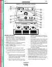
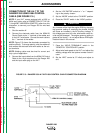
The 240 VAC output can be split to provide two sepa-
rate 120 VAC outputs with a maximum permissible cur-
rent of 33 amps per output to two separate 20 amp
branch circuits. (These circuits cannot be paralleled.)
Output voltage is within ±10% at all loads up to rated
capacity.
The 120 VAC auxiliary power receptacles should only
be used with three-wire, grounded type plugs or
approved double-insulated tools with two-wire plugs.
The current rating of any plug used with the system
must be at least equal to the current capacity of the
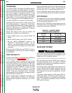
associated receptacle. For extension cord lengths, see
Table B.5.
NOTE: The 240 VAC receptacle has two circuits, each
of which measures 120 VAC to neutral. However, they
are of opposite polarity and cannot be paralleled.
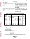
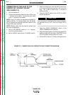
SIMULTANEOUS WELDING AND
AUXILIARY POWER LOADS
The auxiliary power ratings are with no welding load.
Simultaneous welding and power loads are specified in
Table B.4. The permissible currents shown assume
that current is being drawn from either the 120 VAC or
240 VAC supply (not both at the same time).
OPERATION
B-10 B-10
RANGER 250
Return to Section TOC Return to Section TOC Return to Section TOC Return to Section TOC
Return to Master TOC Return to Master TOC Return to Master TOC Return to Master TOC
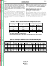
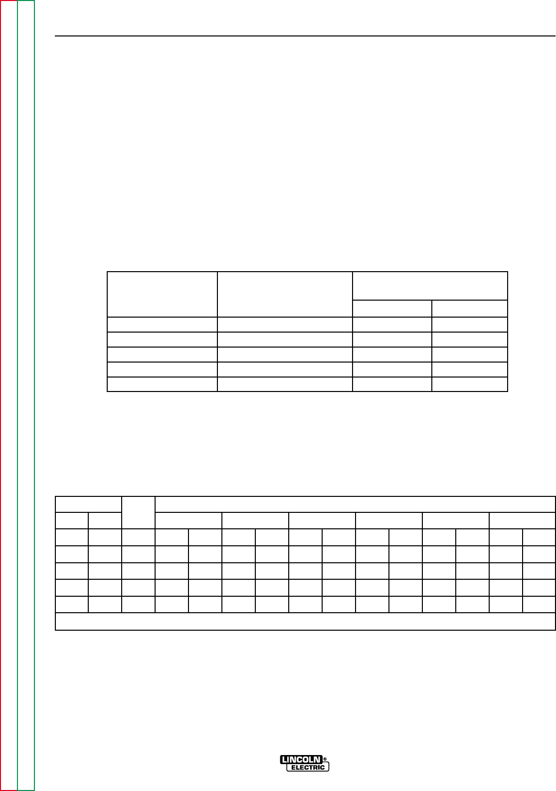
* Each duplex receptacle is limited to 20 amps.
** Not to exceed 25 amps per 120 VAC branch circuit when splitting the 240 VAC output.
TABLE B.4 – RANGER 250 SIMULTANEOUS WELDING AND POWER LOADS
Welding Permissible Power-Watts
Permissible Auxiliary
Output- Amps (Unity Power Factor)
Current in Amps
@ 120 VAC* @ 240 VAC**
0 8000 40* 33
100 5000 40* 21
150 3000 25 12.5
200 1500 12.5 6.3
250 0 0 0
TABLE B.5 – RANGER 250 EXTENSION CORD LENGTH RECOMMENDATIONS
(Use the shortest length extension cord possible sized per the following table)
Current Voltage
Load
Maximum Allowable Cord Length in Ft. (m) for Conductor Size
(Amps) (Volts)
(Watts)
14 AWG 12 AWG 10 AWG 8 AWG 6 AWG 4 AWG
15 120 1800 30 (9) 40 (12) 75 (23) 125 (38) 175 (53) 300 (91)
20 120 2400 30 (9) 50 (15) 88 (27) 138 (42) 225 (69)
15 240 3600 60 (18) 75 (23) 150 (46) 225 (69) 350 (107) 600 (183)
20 240 4800 60 (18) 100 (30) 175 (53) 275 (84) 450 (137)
33 240 8000 60 (18) 100 (30) 175 (53) 250 (76)
Conductor size is based on maximum 2.0% voltage drop.