


TROUBLESHOOTING & REPAIR
F-63 F-63
RANGER 250
Return to Section TOC Return to Section TOC Return to Section TOC Return to Section TOC
Return to Master TOC Return to Master TOC Return to Master TOC Return to Master TOC
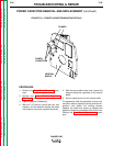
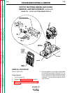
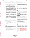
ENGINE/STATOR/ROTOR REMOVAL AND REPLACEMENT (continued)
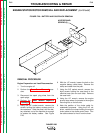
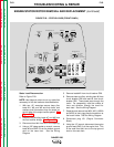
FIGURE F.28 – STATOR LEADS (FRONT PANEL)
Stator Lead Disconnection
Refer to Figure F.28.
NOTE: Use diagonal cutters to cut any cable ties
necessary to free the leads as described below.
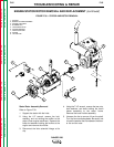
1. With two 1/2" wrenches remove heavy flex
leads W1, W2, and W3 and their bolts, lock
washers and flat washers from the straps on
the left side of the output rectifier plates. See
Figure F.25.
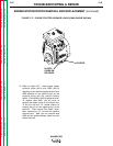
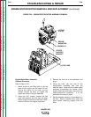
2. Remove field winding leads #7 and #9 from
the field rectifier bridge. See Figure F.9.
3. Disconnect lead #41 from its in-line coupling.
4. Using a 3/8" deep socket or wrench, remove
leads #5 and GND E from the bottom ground
stud on the case front. See the Wiring
Diagram.
5. Remove lead #42 from circuit breaker CB8.
6. Remove stator auxiliary winding lead #6 from
circuit breaker CB6 and lead #3 from circuit
breaker CB5. These leads pass through the
toroid. For reassembly, note the number of
turns and direction through the toroid for
each lead. See the Wiring Diagram.
7. Separate and remove lead #5H, #201, #200A
and #200 at their piggy-back connections at
the brush holder. See the Wiring Diagram.
8. Disconnect plug J51 (Engine Connector
Block).
9. Using the 1/2" wrench, disconnect the engine
ground lead (GND J) at the engine foot. This
is the small lead that runs to the top ground
stud on the case front.
+
HOUR METER
RUN STOP
SWITCH - S1
START BUTTON SWITCH - S2
IDLER SWITCH - S4
OUTPUT CONTROL
212
210A
210
211
211A
210A
210B
210C
J34
1
228
229
PCB7
BATTERY
DISPLAY
J33
230
231
PCB6
THERMAL
DISPLAY
WIRE FEEDER
VOLTMETER
SWITCH - S5
WELD TERMINALS
(CONTACTOR) SWITCH - S3
208A
21
206A
4A
4
2
2A
250
251
224
224B
5G
CASE FRONT - REAR VIEW
R1
10K
R2
10K
5J
77 76
75
277 276
275
ARC CONTROL
WELD MODE SWITCH - S6
1
2
3
4
C1
222
214
218
220
1
221 (KOHLER ONLY)
5J (KOHLER ONLY)
AMPHENOL 2
AMPHENOL 1
B
B
A
A
C
C
D
D
E
E
F
F
KEY
KEY
G
H
I
J
K
L
M
N
GND C
3E
6F
J100
120/240 V AC
5C
3D
GOLD
J102
SILVER
SILVER
5A
GND G
6E
GOLD
J101
5B
GND D
CB5
3A
3A
3
3E
50 AMP 25 AMP
20 AMP
209
CB7
CB1
212A
212
3D, 32
6
6B
6B
CB6
6F
50 AMP
42
CB8
42A
CB2
6E
15 AMP
20 AMP
GND M
GND L
GND J
GND G
GND D
GND C
GND B
GND A
31
5
5A
5B
5C
5F
5G
5H
5K
5L
GND E
SHUNT
204S
206S
POSITIVE OUTPUT STUD
206A
206B
208
208A
208B
NEGATIVE OUTPUT STUD
POS. 1 CV WIRE
POS. 2 PIPE
POS. 3 CC STICK
POS. 4 TOUCH START TIG