


Return to Section TOC Return to Section TOC Return to Section TOC Return to Section TOC
Return to Master TOC Return to Master TOC Return to Master TOC Return to Master TOC
TROUBLESHOOTING & REPAIR
F-31 F-31
RANGER 250
STATOR VOLTAGE TESTS (continued)
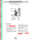
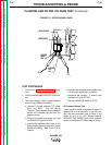
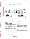
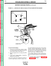
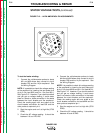
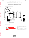
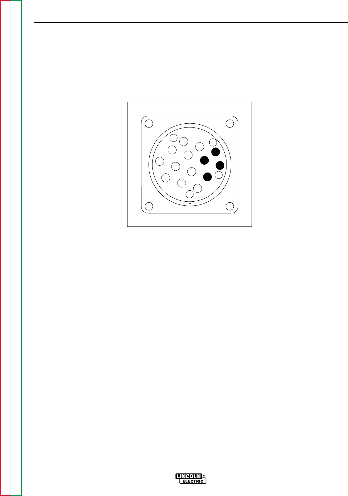
FIGURE F.12 – 14-PIN AMPHENOL PIN ASSIGNMENTS
Z
W
Y
X
K
B
I
H
N
L
C
D
M
G
E
F
A
J
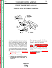
To test the feeder winding:
1. Connect the volt/ohmmeter probes to leads
#31 and #32 where they connect to circuit
breaker CB1 and the 14-pin amphenol. See
the Wiring Diagram.
NOTE: It is possible to check this voltage reading
at the amphenol by inserting the test probe pins
at pin A (for lead #32) and pin J (for lead #31).
See Figure F.12. However, if you use this method
and you get no voltage reading, it could mean
there is a break or loose connection in the leads
between the circuit breaker and the amphenol.
Check the reading again with one probe at the
circuit breaker connection for lead #32 and the
other probe at amphenol pin J.
2. Start the engine and run it at high idle (3700
RPM).
3. Check the AC voltage reading. It should be
between 118 and 126 VAC.
4. Connect the volt/ohmmeter probes to leads
#41A and #42A where they connect to circuit
breaker CB8 and the 14-pin amphenol. See
the Wiring Diagram.
NOTE: It is possible to check this voltage reading
at the amphenol by inserting the test probe pins
at pin K (for lead #42A) and pin I (for lead #41A).
See Figure F.12. However, if you use this method
and you get no voltage reading, it could mean
there is a break or loose connection in the leads
between the circuit breaker and the amphenol.
Check the reading again with one probe at the
circuit breaker connection for lead #42A and the
other probe at amphenol pin I.
5. Start the engine and run it at high idle (3700
RPM).
6. Check the AC voltage reading. It should be
between 40 and 46 VAC.