


TROUBLESHOOTING & REPAIR
F-67 F-67
RANGER 250
Return to Section TOC Return to Section TOC Return to Section TOC Return to Section TOC
Return to Master TOC Return to Master TOC Return to Master TOC Return to Master TOC
ENGINE/STATOR/ROTOR REMOVAL AND REPLACEMENT (continued)
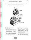
6. Insert the rotor thru-bolt and centering wash-
er. With the torque wrench and socket, tight-
en the bolt to 50 ft lbs. Then recheck all four
engine-stator mounting bolts for tightness.
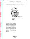
7. Check the rotor-stator air gap with a .017
feeler gauge. The measurement is taken at
the blower end of the rotor before the fan is
reinstalled. (The rotor has two flat sides,
which are not measured for air gap.) Slide in
the gauge. Then rotate the shaft 180
degrees and measure again. If the gauge
does not clear, loosen the rotor thru-bolt and
four engine-stator bolts; retighten the bolts
and recheck the air gap. Repeat until the
proper .017 minimum air gap is achieved.
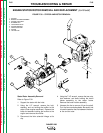
8. Screw the blower fan back onto the end of
the rotor shaft. Be sure the washer is in
place and hand-tighten the fan only.
9. Install the muffler to the engine. Use new
gaskets if necessary. Position the vertical
firewall as you install the muffler. Then
install the 1/2" bolt, washers, and nut that
hold the muffler to the stator frame.
10. Install the side firewalls.
11. Reassemble the idler solenoid linkage.
12. Connect the engine ground strap to the
engine mounting foot.
13. Attach the stator to its bottom support
bracket and reinstall the engine mounting
hardware.
14. Connect the engine starter solenoid leads.
15. Connect the engine choke cable and fuel
line.
16. Install the brush holder assembly and leads.
17. Install the case back.
18. Install the battery. Connect the positive bat-
tery cable first, then the negative battery
cable. BE SURE TO CONNECT THE POS-
ITIVE BATTERY CABLE FIRST.
LEAD RECONNECTION CHECKLIST
Engine
❒ Plug J51
❒ Brush leads #201(-) and 5H (-) and #200A(+)
and #200 (+) at their proper brush holder
connections
Stator
❒ Heavy leads #W1, W2, and W3 to the output
rectifier bridge
❒ Field winding leads #7 and #9 to the field rec-
tifier bridge
❒ Lead #41 to #41A at their in-line coupling
Front Panel
❒ Small green engine ground lead to the top
ground stud on the case front panel (GND J)
❒ Lead #5 and GND E to bottom ground stud
❒ Lead #6 to circuit breaker CB6 and lead #3 to
circuit breaker CB5 through the toroid (Note
number of turns and direction. See the
Wiring Diagram.)
❒ Lead #42 to circuit breaker CB8
GENERAL NOTES ON REASSEMBLY
1. Replace any cable ties cut during disassem-
bly.
2. When installing the battery, connect the pos-
itive battery cable, then the negative battery
cable. BE SURE TO CONNECT THE POSI-
TIVE BATTERY CABLE FIRST.
3. Connect the spark plug wires.
4. Perform the Case Cover Replacement pro-
cedure.
5. Conduct the Retest after Repair procedure,
the following topic in this section of the man-
ual.