


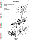

THEORY OF OPERATION
E-4 E-4
RANGER 250
Return to Section TOC Return to Section TOC Return to Section TOC Return to Section TOC
Return to Master TOC Return to Master TOC Return to Master TOC Return to Master TOC
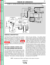
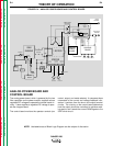
ANALOG POWER BOARD AND
CONTROL BOARD
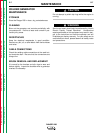
The analog power board, which is powered by the two
filter capacitors on the power module, supplies various
regulated DC voltages to operate the control board cir-
cuitry. It also supplies a regulated DC voltage to oper-
ate the chopper board.
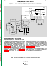
The control board monitors the operator controls (arc
control, output, and mode selector). It compares these
commands to the current and voltage feedback infor-
mation it receives from the shunt and output terminal
circuits. The circuitry on the control board determines
how the output should be controlled to optimize weld-
ing results, and it sends the correct PWM signals to the
IGBT driver circuit.
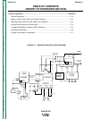
NOTE: Unshaded areas of Block Logic Diagram are the subject of discussion.
FIGURE E.4 – ANALOG POWER BOARD AND CONTROL BOARD
ENGINE
CONTROL
BOARD
ROTOR
STATOR
BATTERY
BOARD
BATTERY
CHOKE
IGBT
MECHANICAL
ROTATIO N
STARTER
I
D
L
E
R
ARC
CONTROL
OUTPUT
CONTROL
MODE
SELECTOR
POWER MODULE
THREE-PHASE
RECTIFIER
WORK
TERMINAL
ELECTRODE
TERMINAL
+
120VAC
RECEPTACLE
240VAC
RECEPTACLE
SLIP
RINGS
TO
CONTROL
BOARD
GAS
OIL
PRESSURE
SWITCH
RUN/STOP
SWITCH
FLYWHEEL
ALTERNATOR
TO CONTROL
BOARD
AMPHENOL
4
2
V
A
C
FIELD
WINDING
AUXILIARY
WINDINGS
WIRE FEED
PWR WNDG
4
2
V
A
C
2
4
0
V
A
C
1
2
0
V
A
C
W
E
L
D W
I
N
D
I
N
G
+
ANALOG
POWER
BOARD
2
0
V
D
C
4
0
TO
1
0
0
V
D
C
FROM
TOROID
CURRENT
SENSOR
SHUNT
F
E
E
D
B
A
C
K
SOL
__
__
REGULATED VOLTAGES
P
W
M
S
I
G
N
A
L
S