


TROUBLESHOOTING & REPAIR
F-54 F-54
RANGER 250
Return to Section TOC Return to Section TOC Return to Section TOC Return to Section TOC
Return to Master TOC Return to Master TOC Return to Master TOC Return to Master TOC
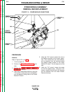
DIODE MODULE REMOVAL AND REPLACEMENT
Removal
Refer to Figure F.23.
1. Remove the Power Module PC Board as
described above.
2. Using the 7/16" wrench, remove the two
outer screws, spring washers, and large flat
washers from the diode module.
3. Using the 9/64" allen wrench, remove the set
screw from the center of the diode module.
4. Remove the diode module from the heat sink.
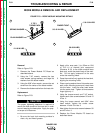
Replacement
Refer to Figure F.23.
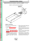
The proper tightening sequence is required to
mount the diode module to the heat sink in order
to avoid warping the base plate. Apply the prop-
er torque to all fasteners.
1. Be sure the heat sink mounting surface is
clean, dry, and free of grease.
2. Apply a thin, even coat (.1 to .25mm or .004
to .010 in) of thermal joint compound
(Penetrax A-13) to the diode module base
plate only, under the plastic body of the mod-
ule. Do not apply compound to the area
under the mounting holes.
3. Press the module firmly against the heat sink,
aligning the mounting holes.
4. Place a spring washer then a flat washer over
each outer mounting screw and insert them
into the holes. Insert the allen head screw
into the center hole. Tighten all three screws
finger-tight only. ➀
5. Using the torque wrench and 7/16" socket,
tighten each outer screw between 5.0 and 10
in-lbs. ➁
6. Using the torque wrench and 9/64" allen
head socket, tighten the center screw
between 12 and 18 in-lbs. ➂
7. Now tighten the two outer screws between 30
and 40 in-lbs. ➃
8. Replace the Power Module PC board as
described above.
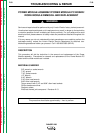
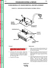
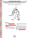
FIGURE F.23 – DIODE MODULE MOUNTING DETAILS
SPRING WASHER
PLAIN WASHER
2 TO 3
TURNS EACH
12-18 IN.LBS.
FINGER TIGHT
5.0-10 IN-LBS.
5.0-10 IN-LBS.
30-40 IN.LBS.
CAUTION
3
1
2
4