


Return to Section TOC Return to Section TOC Return to Section TOC Return to Section TOC
Return to Master TOC Return to Master TOC Return to Master TOC Return to Master TOC
TROUBLESHOOTING & REPAIR
F-7 F-7
RANGER 250
TROUBLESHOOTING GUIDE Observe Safety Guidelines
detailed in the beginning of this manual.
If for any reason you do not understand the test procedures or are unable to perform the test/repairs safely,
contact the Lincoln Electric Service Department for electrical troubleshooting assistance before you proceed. Call
1-800-833-9353.
PROBLEMS
(SYMPTOMS)
POSSIBLE AREAS OF
MISADJUSTMENT(S)
RECOMMENDED
COURSE OF ACTION
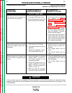
OUTPUT PROBLEMS
The machine has low welding out-
put and low auxiliary output.
1. The engine RPM may be low.
2. Check the brushes for wear and
proper contact to the slip rings.
1. If the engine high idle speed is
low, perform the Engine
Throttle Adjustment Test.
2. Perform the Rotor Resistance
Test.
3. Perform the Flashing and
Rotor Voltage Test. If the rotor
voltage is low, the field capaci-
tor or field bridge may be faulty.
Test and replace if necessary.
See the Wiring Diagram.
4. If the engine high idle RPM is
OK but slows down excessively
under load, then the engine
may have lost horsepower and
be in need of major repair.
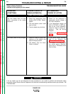
CAUTION
The machine control is still active
when the remote control unit is
connected.
1. This is normal in TIG mode.
2. The remote control unit may be
defective.
3. Check the amphenol connec-
tions and associated wiring.
1. Check Plug J10 on the Control
Board for loose or faulty con-
nections.
2. The bypass board may be
faulty.
3. The Control Board may be
faulty.
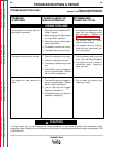
Machine seems to be locked into
the CC mode of operation (stick
mode.)
1. Check the position of the Mode
Selector switch. It must be in
the correct position for the
process being used.
2. Check that jumper plug J3 is
properly installed in the Control
Board. (J3 has a jumper wire
from pin 1 to pin 5.)
3. Make sure plug J2 is properly
connected to the Control Board.
1. Check the Mode Selector switch
and associated wiring. See the
Wiring Diagram.
2. The Control Board may be
faulty.