


TROUBLESHOOTING & REPAIR
F-52 F-52
RANGER 250
Return to Section TOC Return to Section TOC Return to Section TOC Return to Section TOC
Return to Master TOC Return to Master TOC Return to Master TOC Return to Master TOC
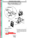
POWER MODULE ASSEMBLY
REMOVAL AND REPLACEMENT (continued)
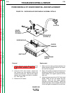
7. Label and remove leads #232 and #233
from the temperature switch.
8. Unscrew plug J50 from the vertical baffle.
Using the phillips head screw driver,
remove the four screws holding the plug to
the vertical baffle. Cut any necessary cable
ties. Then pull the plug and leads away
from the baffle.
9. Using the 3/8" socket wrench, remove the
three screws holding the Power Module
heat sink to its brackets on the vertical baf-
fle. Remove the glastic fan guard, if present
on your machine.
10. Remove the Power Module assembly from
the machine.
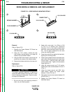
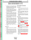
Replacement
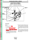
Refer to Figures F.21 and F.22.
1. Mount the heat sink to the brackets on the
vertical baffle with the three 3/8" screws.
Mount the glastic fan guard, if present.
2. Mount plug J50 to the vertical baffle with
four phillips head screws. Connect the plug
and screw it together.
3. Install leads #232 and #233 to the tempera-
ture switch.
4. Using the 7/16" wrench, attach the negative
strap from the power capacitors to the diode
module with two bolts, lock washers, and flat
washers. Using the 7/16" wrench, tighten the
negative strap center nut. Tighten all fasten-
ers to 30-40 in-lbs.
5. Using the 7/16" wrench, attach the positive
straps from the power capacitors to the
Power Module PC board. Tighten the fasten-
ers at the positive terminals of the power
capacitors to between 50 and 60 in-lbs.
6. Mount heavy leads W8 and W9 to the Power
Module PC board with the 7/16" nuts, lock
washers, and flat washers. Apply a thin coat-
ing of electrical thermal joint compound
(Penetrox A-13) to the mating surfaces (but
not the threads). Tighten the fasteners to
between 12 and 18 in-lbs).
7. Replace any cable ties cut at disassembly.
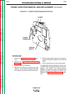
See the procedures below for removal and
replacement of the power module PC board and
diode module. When procedures are complete,
perform the Case Cover Replacement proce-
dure.