


Return to Section TOC Return to Section TOC Return to Section TOC Return to Section TOC
Return to Master TOC Return to Master TOC Return to Master TOC Return to Master TOC
TROUBLESHOOTING & REPAIR
F-5 F-5
RANGER 250
TROUBLESHOOTING GUIDE Observe Safety Guidelines
detailed in the beginning of this manual.
If for any reason you do not understand the test procedures or are unable to perform the test/repairs safely,
contact the Lincoln Electric Service Department for electrical troubleshooting assistance before you proceed. Call
1-800-833-9353.
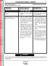
PROBLEMS
(SYMPTOMS)
POSSIBLE AREAS OF
MISADJUSTMENT(S)
RECOMMENDED
COURSE OF ACTION
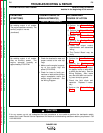
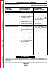
OUTPUT PROBLEMS
No welding output in all modes.
The engine operates normally. The
auxiliary output is normal.
(continued)
5.
Perform the Stator Voltage
Test.
6. Perform the Output Rectifier
Bridge Test.
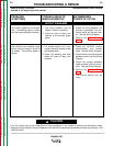
7.
Perform the Power Module
Test.
8. Perform the Analog Power
Board Test.
9. Check the output control
potentiometer and associated
wiring.
10. The Control Board may be
faulty.
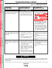
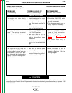
No welding output in all modes.
Also no auxiliary power. The
engine operates normally at
approximately 3700 RPM.
1. Check the brushes for wear and
proper contact to the rotor slip
rings.
2. Make sure the engine is operat-
ing at the correct high idle
speed (3700 RPM).
3. Check for loose or faulty con-
nections or leads at the auxiliary
output receptacles and/or the
welder output terminals. See
the Wiring Diagram.
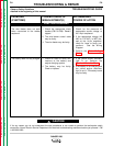
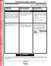
1. Perform the Rotor Resistance
Test.
2. Perform the Flashing and
Rotor Voltage Test. If the
“flashing” voltage is not present,
the battery board or leads #201
or #200 may be faulty. See the
Wiring Diagram. Also, make
sure that lead #5H has continu-
ity (zero ohms) to ground.
3. Check the field diode and
capacitor. Replace if neces-
sary.
4. Perform the Stator Voltage
Test.
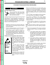
CAUTION