


TROUBLESHOOTING & REPAIR
F-37 F-37
RANGER 250
Return to Section TOC Return to Section TOC Return to Section TOC Return to Section TOC
Return to Master TOC Return to Master TOC Return to Master TOC Return to Master TOC
OUTPUT RECTIFIER BRIDGE TEST (continued)
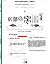
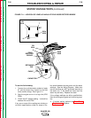
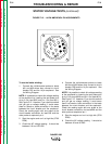
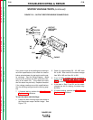
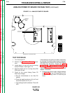
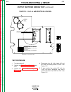
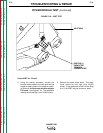
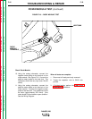
FIGURE F.15 – PLUG J41 AND RESISTOR R3 LOCATIONS
1
1
1
1
1
PCB2
ANALOG POWER
PC BOARD
PCB5
BY-PASS
PC BOARD
J60
J61
J62
J42
J41
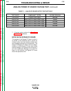
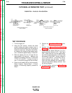
14 2J41 to NEG TERMINAL ON C2 - 85V SUPPLY
13 1J41 to POS TERMINAL ON C2 - 85V SUPPLY
11 1J42 toPIN 3 of P50
105A 2J42 to3J13
5L 4J42 to GND. SCREW
115A 5J42 to 1J13
12 6J42 to PIN 1 of P50
101A 7J42 to 2J13
116A 9J42 to 4J13
118A 10J42 to 5J13
GND
K
GND
L
CHOPPER POWER SUPPLY, 20V
CHOPPER POWER SUPPLY, 20V
WELD BOARD POWER SUPPLY, +5V TO CIRCUIT GROUND
CIRCUIT GROUND
FRAME GROUND
WELD BOARD POWER SUPPLY, +15V TO CIRCUIT GROUND
WELD BOARD POWER SUPPLY, +15V TO CASE GROUND
WELD BOARD POWER SUPPLY, +5V TO CIRCUIT GROUNDWELD BOARD POWER SUPPLY, +5V TO CIRCUIT GROUNDWELD BOARD POWER SUPPLY, +5V TO CIRCUIT GROUND
WELD BOARD POWER SUPPLY, -15V TO CIRCUIT GROUND
CONTROL CIRCUIT
INPUT POWER
C1
C2
RESISTOR R3
(0N BLOWER
SIDE OF
BAFFLER)
BLOWER BAFFLE - SIDE OPPOSITE BLOWER
3
2
4
1
10
9
8
7
6
1
2
3
4
5
J41
J42
TEST PROCEDURE
1. Turn the engine off.
2. Perform the Case Cover Removal proce-
dure.
3. Perform the Power Module Capacitor
Discharge procedure.
4. Disconnect plug J41 (with leads #13 and
#14) from the Analog Power PC board. See
Figure F.15.
5. If your machine has resistor R3, with the
11/32" nut driver, disconnect one end of
resistor R3, either lead #252 or #253. See
Figure F.15.