


TROUBLESHOOTING & REPAIR
F-61 F-61
RANGER 250
Return to Section TOC Return to Section TOC Return to Section TOC Return to Section TOC
Return to Master TOC Return to Master TOC Return to Master TOC Return to Master TOC
ENGINE/STATOR/ROTOR REMOVAL AND REPLACEMENT (continued)
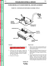
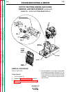
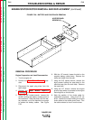
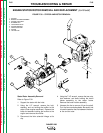
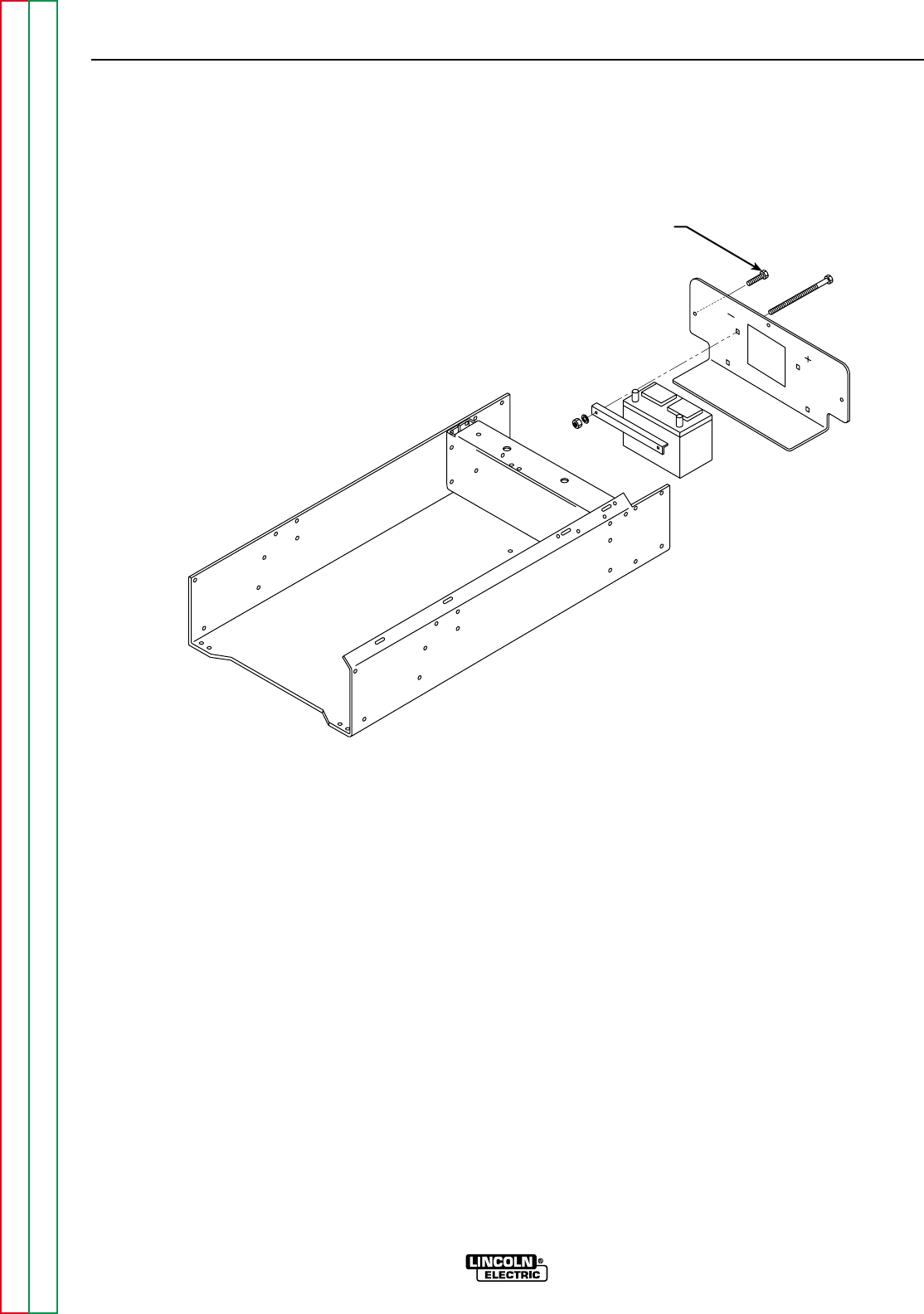
FIGURE F.26 – BATTERY AND CASE BACK REMOVAL
ACCESS PANEL
SCREWS (3)
REMOVAL PROCEDURE
Engine Preparation and Lead Disconnection
1. Turn the engine off.
2. Perform the Case Cover Removal proce-
dure.
3. Disconnect the spark plug wires from the
spark plugs.
4. Perform the Power Module Capacitor
Discharge procedure.
5. Using the 3/8" socket wrench, remove the
screws holding the battery access panel to
the case back. Slide the panel, with the bat-
tery attached, out of the machine far enough
to access the battery cables. See Figure
F.26.
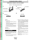
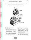
6. With the 1/2" wrench, loosen the bolt on the
negative battery cable clamp. Remove the
clamp and cable from the post.
7. Using the 3/8" socket wrench, remove the
eight screws holding the case back to the
machine base (four on each side). Remove
the case back.
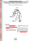
8. Using the 1/2" wrench, remove the engine
ground strap where it connects to the engine
mounting foot on the left side.
9. Note the position of the choke cable for
reassembly purposes. Using the 5/16" nut
driver, remove the clamp holding the engine
choke cable to the choke control lever. Flex
the cable outward to free it from the lever.