


TROUBLESHOOTING & REPAIR
F-56 F-56
RANGER 250
Return to Section TOC Return to Section TOC Return to Section TOC Return to Section TOC
Return to Master TOC Return to Master TOC Return to Master TOC Return to Master TOC
POWER CAPACITOR REMOVAL AND REPLACEMENT (continued)
PROCEDURE
1. Perform the Case Cover Removal proce-
dure.
2. Perform the Power Module Capacitor
Discharge procedure.
3. Label all leads for reassembly.
4. With the 7/16" wrench, remove the nuts, lock
washers, and flat washers holding the leads
and straps to the power capacitor terminals.
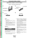
5. With the slot headed screw driver, loosen the
clamps holding the capacitors to the vertical
baffle.
6. Slip the capacitors out of the vertical baffle.
To reassemble, slide the capacitors into the verti-
cal baffle, observe capacitor polarity and lead ori-
entation, and tighten the holding clamps.
Replace the leads and straps as labeled and
tighten the fasteners to between 50 and 60 in-lbs.
Perform the Case Cover Replacement proce-
dure.
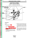
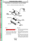
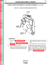
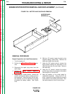
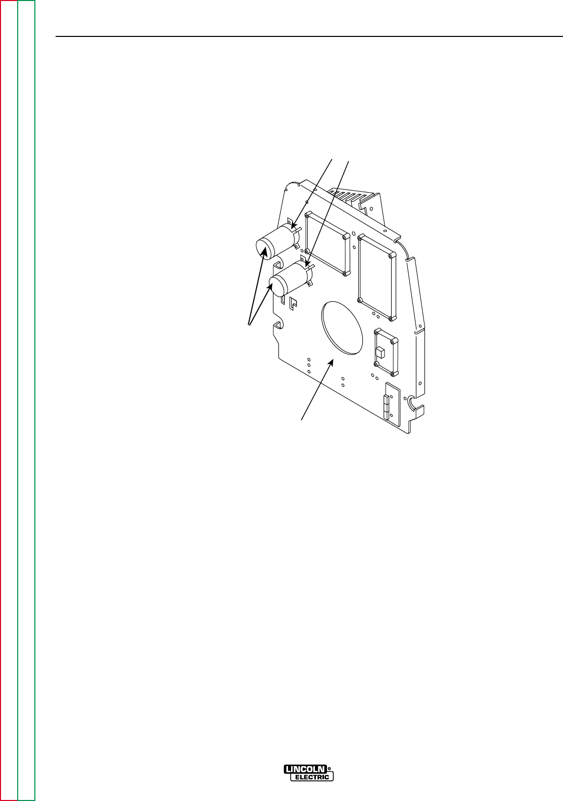
FIGURE F.24 – POWER CAPACITOR MOUNTING DETAILS
VERTICAL
BAFFLE
POWER
CAPACITORS
CLAMPS