


TROUBLESHOOTING & REPAIR
F-16 F-16
RANGER 250
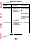
Return to Section TOC Return to Section TOC Return to Section TOC Return to Section TOC
Return to Master TOC Return to Master TOC Return to Master TOC Return to Master TOC
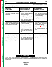
POWER MODULE CAPACITOR DISCHARGE PROCEDURE (continued)
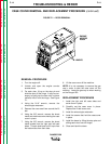
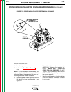
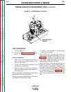
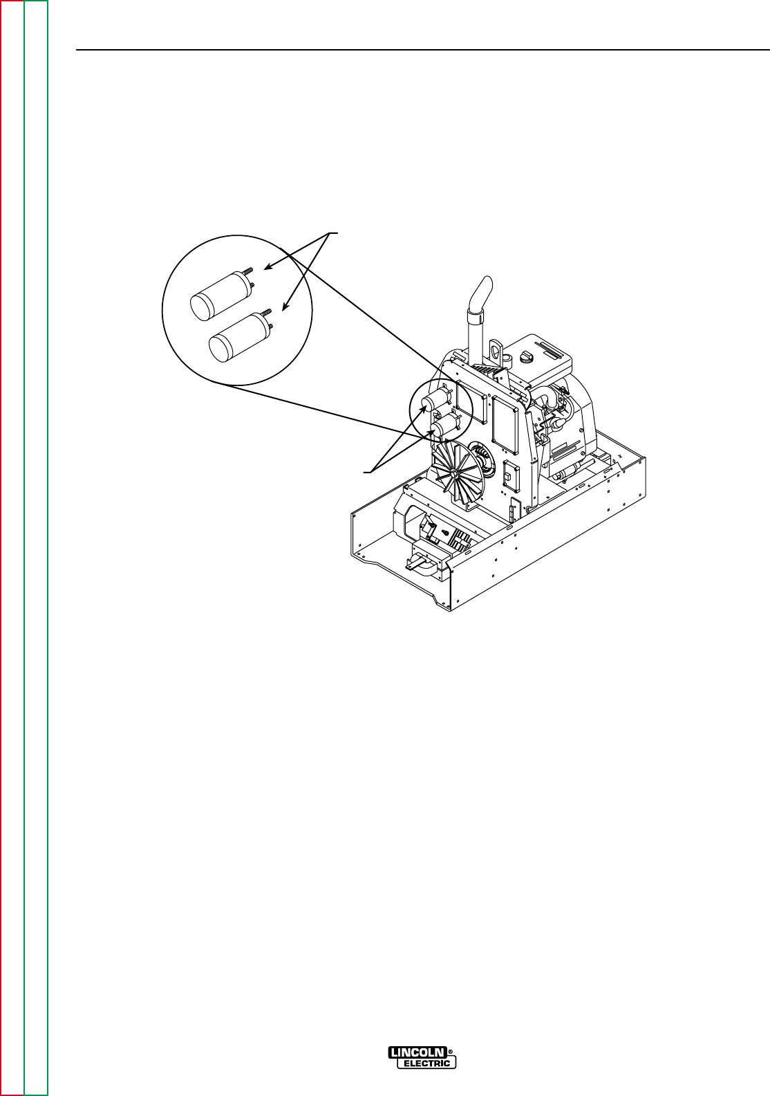
FIGURE F.2 – POWER MODULE CAPACITOR TERMINAL DISCHARGE
SHORT ACROSS
TERMINALS
WITH RESISTOR
POWER
MODULE
CAPACITORS
{
{
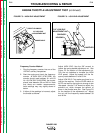
TEST PROCEDURE
1. Turn the engine off.
2. Perform the Case Cover Removal proce-
dure.
NOTE: It is not necessary to remove the gas
cap in order to take the case cover off the
machine. Be sure the gas cap is ON when dis-
charging the power module capacitors.
3. Locate the power module capacitors on the
left side of the inner machine baffle. See
Figure F.2.
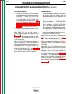
4. Using the resistor and jumper leads,
CAREFULLY discharge the capacitor ter-
minals. NEVER USE A SHORTING
STRAP FOR THIS PURPOSE. DO NOT
TOUCH THE TERMINALS WITH YOUR
BARE HANDS. Repeat the procedure for
the second capacitor.
5. Using the volt/ohmmeter, check the voltage
across the capacitor terminals. It should
be zero volts.