


channels, there is considerable flexibility in the choice of the composite channel protocol and speed. The use of a
synchronous protocol like HDLC provides for error detection and retransmission over the composite link. Thus,
asynchronous terminals, which have no inherent error-recovery capability, can enjoy end-to-end data integrity.
With the implementation of voice and fax information streams into the STDM, an additional technology was needed to
accommodate the time-sensitive nature of voice and fax transmissions. This new technology is called Priority
Statistical Multiplexing (PSM) by Multi-Tech. With this new technology, data packets are limited in length and voice
and fax packets are given priority. The length of the data packet is determined dynamically according to the link speed
preserving the time requirements of normal speech and non-error correcting fax transmissions.
1.3.1.2
Communications
The basic functions of multiplexing are to make communications more efficient, to provide a means of improving
accuracy of asynchronous communications by using synchronous techniques, and to improve data security by
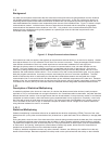
encrypting several data streams into one coded link. Communications using the MMV1600/3200 can be point-to-point
or multipoint. In point-to-point, a MultiMux at a host site is connected to a MultiMux at a remote site. Communications
which you need to concern yourself with include those between the two MultiMuxes designed to carry the data traffic
(composite link), the command modem communications between sites used to control both locations from one location
and any communications between terminals and computers connected to the MultiMuxes.
The channel devices can be any asynchronous RS232 compatible units, from dumb terminals to personal computers
running asynchronous communications software. The connection between the channel devices and the MultiMux is
made through an RS232 interface cable. Asynchronous modems (long haul or short haul), asynchronous modem
emulators and asynchronous line drivers (DCE devices) can be used in this connection (up to 19.2K bps) to extend the
distance between the channel devices and the MultiMux. Due to the channel switching feature of the MultiMux,
channels can be switched to any channels on the remote end. This adds considerable flexibility to your point-to-point
communications. You cannot interconnect channels on the same local MultiMux unit.
The connection between the two MultiMuxes is the composite link with a Data Service Unit (DSU) providing the
interface between the MultiMux and the Digital Data Service (DDS) or dedicated network. The composite data link is
full-duplex and synchronous using HDLC protocol. The composite link can use either dedicated (leased) or DDS lines.
In addition to the internal DSU's available on the MMV1600/3200, you can use any compatible external DSU or
modem. The internal DSU processes serial synchronous digital data over a DDS network, or other four wire unloaded
twisted-pair wiring system. Data transmission on the composite link starts at 2400 bps, doubles to 4800, 9600, 19,200
and finally to 56,000 bps in multipoint and point-to-point applications.
1.4
Product Description
The MultiMux MMV1600/3200 series is available in two basic models: a 16 channel or 32 channel unit with internal
command modem, optional composite link DSUs and two optional voice/fax channels. The MMV1608 MultiMux can
connect up to eight async devices and the MMV1616 up to 16 async devices to its asynchronous channels that transfer
data at speeds up to 19.2K bits per second (bps). The MMV3200 series can connect up to 32 async devices to its
channels. The command modem allows you to configure your async channels, composite link, origin and destination of
the voice channels, and the voice mode of operation. The composite link can be configured for either one or two
internal Digital Service Units (DSUs) or equivalent external DSUs or modems for digital communications over a Digital
Data Service (DDS) or dedicated network. The voice/fax channels allow voice and fax traffic over the same composite
link without the need for a separate voice network.
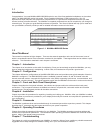
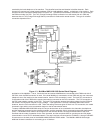
The MMV1600/3200 series has three types of pc boards; the main pc board is called the aggregate pc board, the board
that interfaces to the asynchronous channel devices is the channel board, and the third pc board is the voice/fax board
that connects to the telephone and fax equipment. A simplified block diagram of a MultiMux is shown in Figure 1-3.
The aggregate pc board is in the center of the figure and connects the other two pc boards. The aggregate board is
the mind of the MultiMux; that is, it provides the control and data paths from the channel devices and the voice and fax
traffic from the telephone equipment and fax machines to the composite link and on to the remote location. This board
also provides the interface to the command port for the supervisory console and the command modem interface.
The channel board provides the interface to the asynchronous devices such as pcs, printers, modems, if a device is
remote, and work stations. Each channel board connects up to eight devices to the MultiMux. An MMV1608 MultiMux
has one channel board, MMV1616 has two channel boards to connect up to 16 devices and the maximum is 32 devices
on a MMV3232 MultiMux. The channel board is connected to the aggregate board by two ribbon cables that carry data
and control information between the aggregate board and the channels. Any device with a serial interface can be
connected to a channel board. Each channel board has eight RS232C connectors to connect to the devices.
The voice/fax board connects telephone and fax type equipment to the MultiMux for transmission over the composite
link to a remote location. This board takes the analog voice or fax traffic and converts it to digital information for use by
the aggregate board. Digitized voice or fax traffic from the remote location can also be converted to analog signals and