


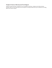
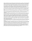
When the voice/fax board is used, connections can be made for either channel 1 or channel 2 or both channels and the
types of connections are the same for both channels. If a PBX is being used at both the local and remote locations and
an E&M trunk connection is desired, then the E&M connections are used for the desired channels. If a PBX is being
used at the local location and a dedicated instrument (telephone or fax machine) is used at the remote location, then
the FXO connection is made to the station side of the PBX and the remote location is connected to the FXS connector
on the back panel of the remote MultiMux. If a dedicated instrument is being used at the both the local and remote
locations for either voice or fax communications over the composite link, then the FXS connection is used.
The composite links need to be connected to a PDN either with internal 56K bps DSUs or equivalent external DSUs or
synchronous modems. If both composite links are being used, they both have to be connected to the PDN. The
internal DSUs are connected to the PDN through the COMPOSITE LINK A or B INTERNAL DSU connector on the back
panel. External DSUs or modems are connected to the PDN by the COMPOSITE LINK A or B EXTERNAL MODEM/
DSU connector on the back panel and if the DSU or modem is V.35 compatible, the shunt on the aggregate board
needs to be moved from the RS232C position to the V.35 position. There is a shunt for composite link A and composite
link B.
The supervisory console is connected to the aggregate board through the COMMAND PORT connector on the back
panel. The supervisory console connection is also an RS232 connection. This completes a typical hardware setup for
a MultiMux. Now the MultiMux has to be configured to talk to the channel devices and communicate over the
composite link.
Configuration of a MultiMux is accomplished through a combination of setting DIP switches behind the front panel and
software commands entered through the supervisory console. The DIP switches determine whether the MultiMux is an
eight, sixteen, twenty-four or thirty-two channel multiplexer, whether the composite link devices are internal DSUs or
external devices, whether or not the command modem will accept remote access, etc. The DIP switches control the
hardware setup and the operating setup is controlled through software commands. The software commands are
entered at a terminal connected to the COMMAND PORT which are transferred to either the command processor or
command modem in the MultiMux. The software commands are AT commands that configure the channel devices to
communicate with the MultiMux and configure the composite link devices to communicate with the PDN. To configure
a channel device, the correct channel speed has to be established, number of data and stop bits in a word determined,
the type of flow control used and whether or not pacing is active. These are just some of the AT commands that are
used to configure the channel devices.
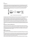
When the MultiMux MMV1600/3200 series is powered up, the command processor transfers the stored configuration of
the channel devices to the data processor. The data processor takes the configuration information and configures each
channel for its particular conditions. The composite link has to be configured for its parameters before data can be
transferred.
The composite link parameters are determined by more than just AT commands transferred to the command processor.
The composite link parameters are determined by what type of device is used, whether it is internal or external, speed,
what type of remote multiplexer we are communicating with and a number of line conditioning parameters. The type of
device used as the composite link device is determined by whether the device is internal or external which is
established by DIP switch settings and by the type of device installed in the MultiMux or connected to the EXTERNAL
COMPOSITE LINK RS232C/V.35 connector on the back panel. If an internal composite link DSU is installed in the
MultiMux, the DIP switch would be set for an internal composite link DSU and a DSU speed select AT command
($DSUA/BSPxxxxx) would determine the operational speed of the DSU. The MultiMux MMV1600/3200 series is now
ready to transfer data from its async devices through an internal composite link DSU.