


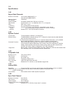
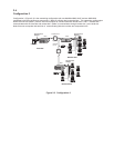

2.4
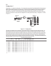
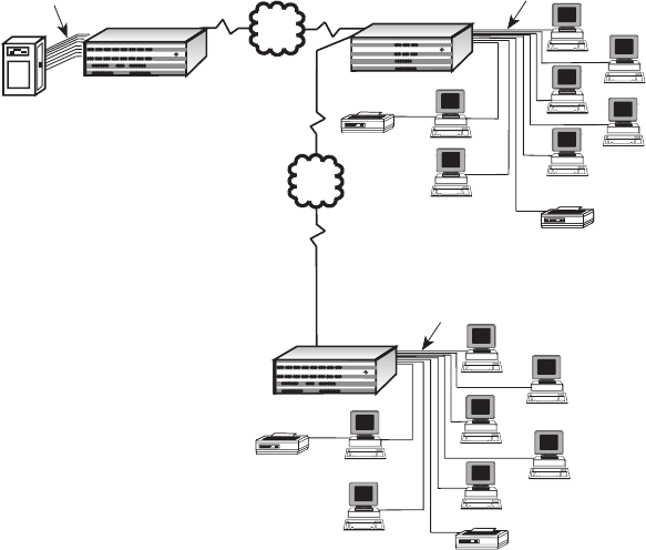
Configuration 3
Configuration 3 (Figure 2-3) is the networking configuration with one MultiMux MMV1616C and two MMV1608
multiplexers with the multiplexer at remote site 1 (Node 2) utilizing dual composite links. This networking configuration
allows the local site (Node 1) with the host minicomputer to communicate with remote sites 1 and 2. Remote site 1
communicates with the local site and remote site 2 (Node 3) communicates through remote site 1 to the local site.
Node 2 has two composite links with link A communicating with the local site and composite link B
Channel 9 Channel 10 Channel 11 Channel 12
Channel 13 Channel 14 Channel 15
Channel 16
Channel 1 Channel 2
Channel 3 Channel 4
Channel 5 Channel 6 Channel 7 Channel 8
Composite Link A Composite Link B
Command Modem
Voice/Fax Channel 1
Voice/Fax Channel 2
MultiMux 16
Data/Voice/Fax
Statistical Multiplexer
Systems
MultiTech
®
Local Site
Digital Line
Asynchronous
Channel
MultiMux MMV1616
PDN
Composite Link A
Composite
Link B
Remote Site 1
Minicomputer
PDN
Terminal
Asynchronous
Channel
Terminal
Terminal
Printer
Terminal
Terminal
Terminal
Terminal
Printer
Channel 9 Channel 10 Channel 11 Channel 12
Channel 13 Channel 14 Channel 15
Channel 16
Channel 1 Channel 2
Channel 3 Channel 4
Channel 5 Channel 6 Channel 7 Channel 8
Composite Link A Composite Link B
Command Modem
Voice/Fax Channel 1
Voice/Fax Channel 2
MultiMux 16
Data/Voice/Fax
Statistical Multiplexer
Systems
MultiTech
®
MultiMux MMV1608
Remote Site 2
Channel 16
Channel 8
Composite Link B
Voice/Fax Channel 2
MultiMux 16
Data/Voice/Fax
Statistical Multiplexer
Systems
MultiTech
®
Asynchronous
Channel
Printer
Printer
Terminal
Printer
MultiMux MMV1608
Terminal
Terminal
Terminal
Terminal
Terminal
Terminal
Node 1
Node 2
Node 3
Figure 2-3. Configuration 3