


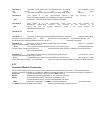
Test Mode 7 Test Mode 7 is the Switch and LED operational test. By running your MultiMux in this
test mode, you can switch the eight
&T7 DIP-switches and verify that they work by corresponding LEDs being lit.
Test Mode 8 Test Mode 8 is the Non-Volatile Memory test. Its function is to
check the proper operation of the MultiMuxs storage of operational
&T8 parameters. This test will overwrite the stored parameters.
Test Mode 9 Test Mode 9 is the Watch-Dog Timer test. This test checks the
MultiMuxs Watch-Dog circuitry. The function of the circuitry is to
&T9 return the mux to normal operating mode if, for some reason, its
operation becomes erratic.
Test Mode 10 Not used.
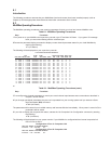
Test Mode 11 Test mode 11 is the local channel test which checks the operation of all channels (cabling,
connection, etc) by outputting "The &T11 Quick Brown Fox Jumped Over..." to all channel devices. You
should receive the complete sentence each time an &T11 command is executed.
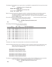
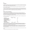
Test Mode 12 Test mode 12 is the voice/fax loopback test (if the voice/fax feature is installed).
When this test is initiated, voice/fax channel
&T12 1 will communicate with voice/fax channel 2 and vice/versa on the same MultiMux unit.
You will need to configure the local and remote interface types (FXS,FXO, E&M) that you wish to test on
each voice/fax channel.
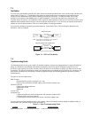
Test Mode 13 Test Mode 13 is the local loop test that receives data from a synchronous device
and loops that data back to the sync device.
&T13 The MultiMux has to have port B configured as a synchronous data channel in order
for this test mode to function. To exit the test mode, you need to reset the MultiMux by entering a ATZ command.
5.2.7
Command Modem Commands
The command modem select and remote access commands are described in this section. The command modem
accepts commands at speeds up to 2400 bps. Additional command modem AT commands are provided in Appendix D.
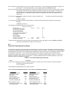
Command The Command Modem Select command #MA1 sends all
Modem subsequent commands generated on your supervisory console
Select to the command modem. The various commands for the
command modem are AT command set compatible with those
#MA described in Appendix F. The #MA1 command enables the command modem.
The #MA0 command disables the command modem input and hangs up the phone line.