


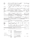
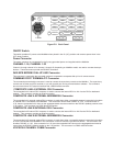
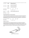
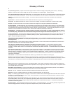
The aggregate board 8-position DIP switch SW-5 is shown in Figure E-3 and the function of each position is as follows:
Switch position 1: Closed Initiate Downline Load Off
Open(UP) Initiate Downline Load On
(used for downline loading only)
Switch position 2: Closed External Link A Device Selected
Open (UP) Internal Link A DSU Selected
Switch Position 3: Closed External Link B Device Selected
Open (UP) Internal Link B DSU Selected
Channel # 8 16 24 32
Switch Position 4: C O C O
Switch Position 5: C C O O
C= Closed, O=Open
Switch Position 6: Closed Disable Command Modem Remote Access
Open (UP) Enable Command Modem Remote Access
(default)
Switch Position 7: Not Used
Switch Position 8: Not Used
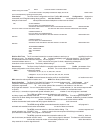
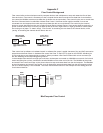
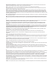
Channel Board Number of Channels Switch
The Channel board four-position DIP switch determines which channel numbers a particular channel board represents.
The first channel board needs to be installed in the third slot from the bottom of the chassis and the 4-position DIP
switch on that board has to be set with switch positions SW-1 and SW-2 in the closed position. If the MultiMux has 16
channels, then two channel boards are installed in the chassis and the channel board in the fourth slot from the bottom
of the chassis has switch position SW-1 in the open position and SW-2 in the closed position. The function of the
switch is as follows:
Channel # 1-8 9-16 17-24 25-32
Switch Position 1: C O C O
Switch Position 2: C C O O
C= Closed, O=Open
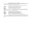
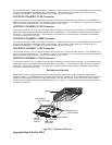
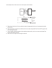
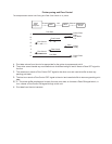
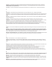
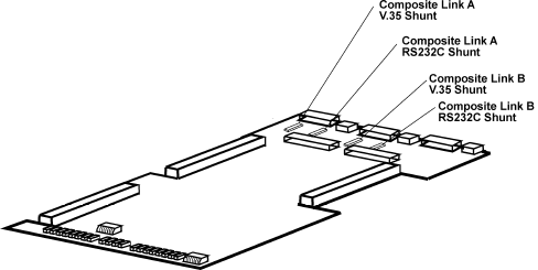
RS232C/V.35 Shunt
An external composite link modem or DSU with either an RS232C/V.24 or a V.35 interface can be connected to a
MultiMux MMV1600/3200 series. The aggregate board has four shunt locations on the board, two positions for
composite link A and two for composite link B and each link can connect either an RS232C or a V.35 interface. When
an external composite link modem with an RS232C/V.24 interface is connected to one of the composite links, the V.24
shunt for that composite link is installed on the aggregate board. When the external composite link modem or DSU has
a V.35 interface, the shunt for that composite link has to be moved from the default position (RS232C/V.24) to the V.35
position. The shunts are shown in Figure E-4. The factory default position for the shunts is in the RS232C/V.24
position.
Figure E-4. RS232C/V.35 Shunts