


4.1
Introduction
This chapter explains how to unpack and install your MultiMux cabinet.
4.2
Unpacking
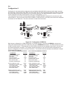
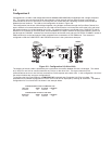
Unpack and check all the items in the MultiMux shipping list to ensure that you have received the correct options and
accessories.
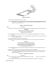
MultiMux Components
A. MultiMux Cabinet
B. Owner's Manual
C. Power cord
D. RJ48 phone cable (for internal DSU)
E. RJ11 phone cable (for internal modem)
F. Composite Link cable ( for external link device)
G. E&M (I-V) Voice/Fax Channel cable (2)
Inspect the MultiMux cabinet for visible shipping damage. If damage is observed, do not power-on the unit; contact
Multi-Tech's Tech Support for advice (refer to Chapter 8). If no damage is observed, place the MultiMux cabinet in its
final location.
Save the packing material for possible future use (e.g., return or relocation).
4.3
Installation Procedure
The installation procedure is organized to cable the MultiMux first, then, if a V.35 interface is used, procedures on how
move the V.24/V35 shunt from its default position to the V.35 position, and finally how to configure the MultiMux. The
cabling procedure is provided in Table 4-1. The V.35 interface procedure is provided in Table 4-2. How to configure
the MultiMux is provided in Table 4-3.
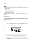
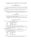
Table 4-1. Cabling Procedure
Step Procedure
Composite Link
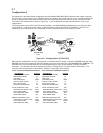
1 Internal DSU on Port A or B - Composite Link
If your MultiMux has internal DSU(s), connect the RJ48 cable shipped with your MultiMux to the COMPOSITE
LINK A or B INTERNAL DSU connector(s) on the back panel of the MultiMux and to your phone line.
Proceed to cabling either the sync data channel or the async channels.
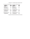
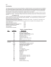
Table 4-1. Cabling Procedure
Step Procedure
MultiTech®
CHANNEL 14
CHANNEL 10
CHANNEL 13
CHANNEL 9
CHANNEL 16
CHANNEL 12
CHANNEL 15
CHANNEL 11
CHANNEL 6
CHANNEL 2
CHANNEL 5
CHANNEL 1
CHANNEL 8
CHANNEL 4
CHANNEL 7
CHANNEL 3
ON
OFF
Systems
MultiMux16™
CAUTION
F-GND
COMPOSITE LINK B
INTERNAL
(RS232C/V.35)
EXTERNAL MODEM/DSU
DSU
COMMAND PORT
TERMINAL/PC
2400 BPS
MODEM
DIAL-UP
LINE
COMPOSITE LINK A
INTERNAL
(RS232C/V.35)
EXTERNAL MODEM/DSU
DSU
E&M
VOICE/FAX CHANNEL 1
FXO
FXS
E&M
VOICE/FAX CHANNEL 2
FXO FXS
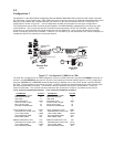
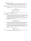
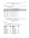
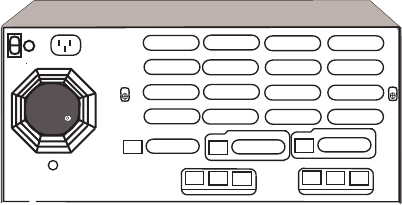
Figure 4-1. Back Panel
External Modem/DSU with RS232C Interface
If either composite link is being connected to an external modem or DSU with an RS232C interface, connect
the composite link cable shipped with your MultiMux to the COMPOSITE LINK A or B (RS232C/V.35)
EXTERNAL MODEM/DSU connector(s) on the back panel and to the RS232 connector on the
external link device(s). Proceed to cabling either the sync data channel or the async channels.
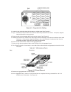
External Modem/DSU with V.35 Interface
If either composite link is being connected to an external modem or DSU with a V.35 interface, refer to Table
4-2 to change the position of the V.24/V.35 shunt. Proceed to cabling either the sync data channel or
the async channels.