


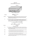
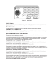
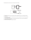
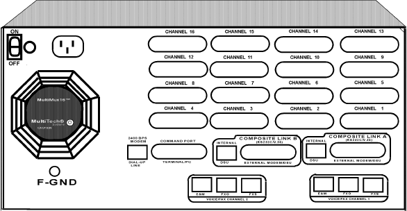
Figure E-2. Back Panel
ON/OFF Switch
This switch provides AC power to the MultiMux when placed in the On (UP) position and removes power when in the
OFF (down) position.
Power Connector
The power connector is a receptacle for the 3-prong grounded power cord supplied with the MultiMux.
CHANNEL 1-16, CHANNEL 1-32
Channel 1 through channel 16 or channel 1 through 32, depending on MultiMux model, are used to connect the async
devices. These connectors provide the RS232C connection.
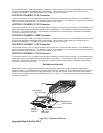
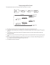
2400 BPS MODEM DIAL-UP LINE Connector
This connector is used when the command modem is connected to a separate dial-up line for remote access.
COMMAND PORT TERMINAL/PC Connector
The command port terminal/pc connector is used to connect the supervisory console to the MultiMux. The supervisory
console can be either an ASCII terminal or a pc with a serial port running communications software. The command
port connector has a DCE physical interface with a DB25 female connector.
COMPOSITE LINK A INTERNAL DSU Connector
The composite link A internal DSU connector is used to connect the internal DSU on link A to the DDS or dedicated
network . This connector provides an RJ48 connection.
COMPOSITE LINK A EXTERNAL MODEM/DSU Connector
The composite link A external modem/DSU connector is used when either a compatible external composite link modem
or external DSU is connected to the MultiMux. This connection can be either RS232C or V.35. If the connection is
V.35, then the composite link A shunt on the aggregate board must be moved from the RS232C (default) position to the
V.35 position. This connector is a DB25 female connection.
COMPOSITE LINK B INTERNAL DSU Connector
The composite link B internal DSU connector is used to connect the internal DSU on link B to the DDS or dedicated
network . This connector provides an RJ48 connection.
COMPOSITE LINK B EXTERNAL MODEM/DSU Connector
The composite link B external modem/DSU connector is used when either a compatible external composite link modem
or DSU is connected to the MultiMux or the connection is used to connect a synchronous device. This connection can
be either RS232C or V.35. If the connection is V.35, then the composite link B shunt on the aggregate board must be
moved from the RS232C (default) position to the V.35 position. This connector is a DB25 male connection.
VOICE/FAX CHANNEL 2 E&M Connector