


2.9
Configuration 8
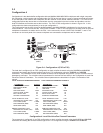
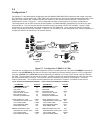
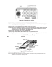
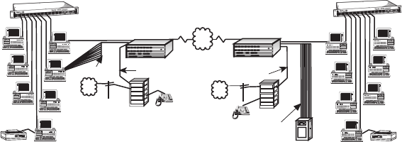
Configuration 8 is a LAN to LAN configuration with two MultiMux MMV1608C/56/V multiplexers with a single composite
link. The muxes are connecting two local area networks (LANs) through the Sync Data Channel, connecting a
communications server on one LAN to a minicomputer at a remote site and connecting voice/fax communications
between the two locations. The LAN to LAN configuration is shown in Figure 2-8.
This configuration has the two LANs bridged together using bridges connected through the Sync Data Channel, the
async channels of communications server on one LAN are connected to a minicomputer at the other LAN, and voice/
fax communications is provided between the LANs. The external bridges are connected to the COMPOSITE LINK B
RS232C/V.35 connector on the back panel of both MultiMuxes, the async channels of the communications server are
tied through the CHANNEL connectors to the minicomputer at the other end, and the VOICE/FAX CHANNEL 1and/or 2
E&M connector(s) on the back panel of both multiplexers are connected to a PBX E&M trunk. The muxes are
configured so that the COMPOSITE LINK B RS232 connector is the synchronous data port.
Composite Link
PDN
Voice/Fax Channel
Telephone
Multiplexer
Channel 9 Channel 10Channel 11 Channel 12
Channel 13 Channel 14 Channel 15
Channel 16
Channel 1 Channel 2
Channel 3 Channel 4
Channel 5 Channel 6 Channel 7 Channel 8
Composite Link A Composite Link B
Command Modem
Voice/Fax Channel 1
Voice/Fax Channel 2
MultiMux 16
Data/Voice/Fax
Statistical Multiplexer
Systems
MultiTech
®
PSTN
PBX
Trunk
Trunk
Station
Trunk
Station
File Server
Print Server
LAN PC
LAN PC
LAN PC
Printer
Communications
Server
Ethernet
Concentrator
Voice/Fax Channel
Multiplexer
Channel 9 Channel 10
Channel 11 Channel 12
Channel 13 Channel 14 Channel 15
Channel 16
Channel 1 Channel 2
Channel 3 Channel 4
Channel 5 Channel 6 Channel 7 Channel 8
Composite Link A Composite Link B
Command Modem
Voice/Fax Channel 1
Voice/Fax Channel 2
MultiMux 16
Data/Voice/Fax
Statistical Multiplexer
Systems
MultiTech
®
Telephone
PBX
Trunk
Trunk
Station
Trunk
Station
PSTN
Bridge
File Server
Print Server
LAN PC
LAN PC
LAN PC
LAN PC
Printer
Ethernet
Concentrator
Bridge
Minicomputer
Async
Channels
Async
Channels
Digital Line
SDLC Sync
Channel
SDLC Sync
Channel
Figure 2-8. Configuration 8 (LAN to LAN)
The bridging of the two LANs is provided by the synchronous connection between the two LAN bridges. This allows
any LAN pc on one LAN to communicate with any LAN pc on the other LAN. The async channels of the
communications server on one LAN are connected to a minicomputer at the other LAN. In this configuration, the voice/
fax communications are set up per configuration 5.
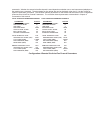
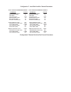
To configure the Sync Data Channel, the $MUXBSYNC command sets Composite Link B for sync data. The
parameters for the default configuration of Port A and Port B can be displayed by entering $L command. The default
configuration for Port A and Port B is shown in the example below.
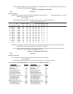
CONFIGURATION OF PORT A: COMPOSITE LINK
DSU TYPE SPEED CLOCKING LOOPBACK
EXTERNAL 56K INTERNAL OFF
CONFIGURATION OF PORT B: SYNC DATA
PROTOCOL SPEED CLOCKING LOOPBACK
ANY SDLC 56K INTERNAL OFF