


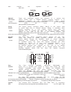

Xon/Xoff Flow Control and Pacing, you will
F11-F12 end up with Xon/Xoff Pacing, and with CTS Flow Control plus Pacing, data flow will
be controlled by the presence of the DTR (pin 20) signal on the RS232 interface. F11 turns on Inverted
DTR so that a high signal stops data flow and a low starts data flow. F12 turns off Inverted DTR so
that it acts normal (high on and low off). If Flow Control is off, Pacing cannot be turned on. If
Pacing is off, inverted DTR cannot be turned on.
Xoff/First F13 is a special pacing command that is called X/off First
Char. Character pacing. Selecting F13 causes the MultiMux to stop
data flow to the channel device upon receipt of a Xoff Character.
F13-F14 The next character from the channel device will start data (it does not have to be an Xon
Character). F14 will turn off this feature.
Identification The Identification commands identify the type of MultiMux. This
Commands information is valuable when communicating with Multi-Tech's
Technical Support personnel about your unit or its performance. I0-2 The l0 command
identifies the product. The I1 command indicates the Aggregate board firmware version. The I2
command indicates the Voice/Fax firmware version.
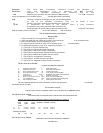
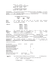
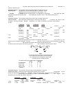
List Channel The List Channel Parameters command causes the MultiMux
Parameters to display the condition of the parameters for each channel on the
systems supervisory console as shown in the following example.
L-L0 To display the parameters for an individual channel, say channel
L1-L32 three, you would enter ATL3 and hit your Return key. To display
the parameters for all of the channels, enter ATL0 and then hit
your Return key.
Local Channel Parameters/ Node # 01
STP FLOW ENQ/ PASS PASS DEST DEST LINK
CHN SPD WD BIT PAR CTRL ACK ECHO PACE EIA XON CHN NODE A/B
01 19200 8 1 NONE CTS OFF OFF OFF OFF OFF 01 02 A
02 19200 8 1 NONE CTS OFF OFF OFF OFF OFF 02 02 A
03 19200 8 1 NONE CTS OFF OFF OFF OFF OFF 03 02 A
04 19200 8 1 NONE CTS OFF OFF OFF OFF OFF 04 02 A
05 19200 8 1 NONE CTS OFF OFF OFF OFF OFF 05 02 A
06 19200 8 1 NONE CTS OFF OFF OFF OFF OFF 06 02 A
07 19200 8 1 NONE CTS OFF OFF OFF OFF OFF 07 02 A
08 19200 8 1 NONE CTS OFF OFF OFF OFF OFF 08 02 A
09 19200 8 1 NONE CTS OFF OFF OFF OFF OFF 09 02 A
10 19200 8 1 NONE CTS OFF OFF OFF OFF OFF 10 02 A
11 19200 8 1 NONE CTS OFF OFF OFF OFF OFF 11 02 A
12 19200 8 1 NONE CTS OFF OFF OFF OFF OFF 12 02 A
13 19200 8 1 NONE CTS OFF OFF OFF OFF OFF 13 02 A
14 19200 8 1 NONE CTS OFF OFF OFF OFF OFF 14 02 A
15 19200 8 1 NONE CTS OFF OFF OFF OFF OFF 15 02 A
16 19200 8 1 NONE CTS OFF OFF OFF OFF OFF 16 02 A
OK
Modem Link This parameter specifies which link modem/DSU (link A, link B Used or Dynamic) each
channel will use for data communications. Links should be load balanced so that heavy traffic channels are
MLA/B/D not all using the same link. The MLD command selects dynamic channel selection
which permits the MultiMux to pick the least busy link per channel. When one channel is dynamic, all must be
dynamic. Works only in point-to-point networks and both muxes must be set to MLD.
Parity The Parity Select commands set the parity of MultiMux opera-
Select tions. Under normal operations (default conditions) parity is off
and word length is set at eight bits. Since the MultiMux is
P0-2 intended to be transparent to channel device operation, this combination will pass
parity information to the channel devices. The P0 command turns parity off, P1 sets odd parity and P2 sets
it at even.
Response The Response Time Priority command determines how long the
Time mux will wait to send data from channel devices relative to each
Priority other. An R0 setting is the shortest and R3 the longest. The
Response Time Priority commands ensure that channel
R operations which require heavy data transfers, such as program transmissions or print