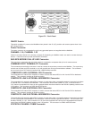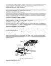
The voice/fax channel 2 E&M (Ear and Mouth) connector is used to connect channel 2 of the MultiMux to the trunk side
of the local private branch exchange (PBX, a small switch). This connector is used when the voice/fax feature is
included in the MultiMux. The E&M connector is an RJ48S 8-position keyed jack.
VOICE/FAX CHANNEL 2 FXS Connector
The voice/fax channel 2 FXS (Foreign Exchange Station) connector is used to connect channel 2 of the MultiMux to a
station instrument (telephone, KTS - key telephone system, or fax machine). This connector is used when the voice/fax
feature is included in the MultiMux. The FXS connector is an RJ11 jack.
VOICE/FAX CHANNEL 2 FXO Connector
The voice/fax channel 2 FXO (Foreign Exchange Office) connector is used to connect channel 2 of the MultiMux to the
station side of the local private branch exchange (PBX, a small switch). This connection is also commonly referred to
as an OPX - Off Premises Extension. This connector is used when the voice/fax feature is included in the MultiMux.
The FXO connector is an RJ11 jack.
VOICE/FAX CHANNEL 1 E&M Connector
The voice/fax channel 1 E&M (Ear and Mouth) connector is used to connect channel 1 of the MultiMux to the trunk side
of the local private branch exchange (PBX, a small switch). This connector is used when the voice/fax feature is
included in the MultiMux. The E&M connector is an RJ48S 8-position keyed jack.
VOICE/FAX CHANNEL 1 FXS Connector
The voice/fax channel 1 FXS (Foreign Exchange Station) connector is used to connect channel 1 of the MultiMux to a
station instrument (telephone, KTS - key telephone system, or fax machine). This connector is used when the voice/fax
feature is included in the MultiMux. The FXS connector is an RJ11 jack.
VOICE/FAX CHANNEL 1 FXO Connector
The voice/fax channel 1 FXO (Foreign Exchange Office) connector is used to connect channel 1 of the MultiMux to the
station side of the local private branch exchange (PBX, a small switch). This connection is also commonly referred to
as an OPX - Off Premises Exchange. This connector is used when the voice/fax feature is included in the MultiMux.
The FXO connector is an RJ11 jack.
Switches and shunts
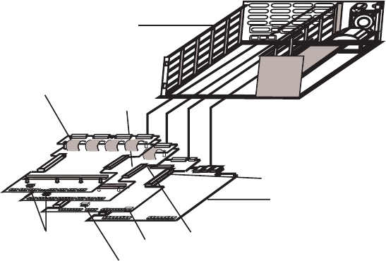
Switch settings can be changed by taking off the front panel and locating the switches on either the aggregate or
channel board(s). The initiate downline load, external/internal DSU, channel size, and remote access to the command
modem DIP switches are located on the Aggregate board. The channel board(s) contian the switches that indicate
which channel numbers that particular board represents, 1-8, 9-16 etc. The pc board orientation, switches and shunts
are shown in Figure E-3.
Voice/Fax Board
Aggregate Board
Channel Board
Channel Board
Switch SW-5
Switch SW-6
(Future Use)
V.24/V35 Shunts
Chassis
Channel
Designation
Switches
Figure E-3. Switches and Shunts
Aggregate Board Switch SW-5


