


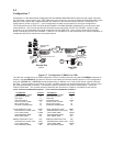
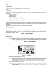
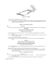
3 If you are connecting a supervisory console to the MultiMux, connect a terminal or PC to the COMMAND
PORT connector via an appropriate RS232C cable. The PC must be running communications
software.
Note
Any cables connected to the computer should be
shielded to reduce interference.
4 Apply power to the supervisory console and enter AT and then hit Return. If you get an OK message back,
you are communicating with the Command Port. The Command Port operates at up to 19.2K bps.
Command Modem
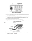
5 To connect the built-in command modem to a standard phone line, connect the RJ11 cable to the 2400 BPS
MODEM DIAL-UP LINE connector on the back panel of the MultiMux and the phone jack.
Composite Link
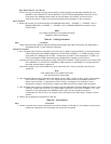
6 Verify that the FC channel LEDs on the front panel flash on for a few seconds and then go out.
7 Verify that the CD, RCV, XMT, CTS LEDs on the composite link (A or B) that you have connected are on and
the RD LED goes off for that link. Proceed to configuring the Sync Data Channel or the Async
Channels.
Note
This verifies that the composite link
is up and working.
If the RD LED stays lit, the composite link device is not configured to communicate with the link, configure the
internal DSU. Proceed to configuring the composite link.
If the XMT and CTS LEDs lite for composite link A or B and the RD LED goes off, the remote mux is not
powered on or the remote DSU is not configured for the composite link. Proceed to configuring the
composite link.
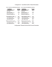
Table 4-3. Configuration Procedure
Step Procedure
8 Enter the List Composite Link Configuration command ($L) to display the default configuration of Composite
Link A and B. The display may appear as follows:
CONFIGURATION OF PORT A: COMPOSITE LINK
DSU TYPE SPEED CLOCKING LOOPBACK
EXTERNAL 128K INTERNAL OFF
CONFIGURATION OF PORT B: COMPOSITE LINK
DSU TYPE SPEED CLOCKING LOOPBACK
EXTERNAL 64K INTERNAL OFF
9 Based on the listed conditions for the composite links, reconfigure the parameters to match your actual
composite link requirements by entering commands as described in Chapter 5.
As you change parameters, they will not actually be incorporated into your running system until you execute a
Store New Parameters (&W) command.
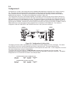
Sync Data Channel - Port B only
10 To configure port B as the Synchronous Data Channel, enter $MUXBSYNC command.
11 Enter a Store Parameter (&W) command and then reset the MultiMux by entering a reset (Z) command or
powering the MultiMux off and back on.
12 Enter $L command again to redisplay the configuration. The display appears as follows:
CONFIGURATION OF PORT A: COMPOSITE LINK
DSU TYPE SPEED CLOCKING LOOPBACK
EXTERNAL 56K INTERNAL OFF
CONFIGURATION OF PORT B: SYNC DATA
PROTOCOL SPEED CLOCKING LOOPBACK
ANY SDLC 56K INTERNAL OFF
13 Based on the listed conditions for the Sync Data Channel, reconfigure the parameters to match your actual
Sync Data Channel requirements by entering commands as described in Chapter 5.