


5.1
Introduction
This chapter presents a command summary followed by a detailed description of each command used in the MultiMux.
Each command line must begin with a prefix of AT and may contain any number of commands in a string (no spaces)
up to a limit of 40 characters. Most commands include a value and are part of the 40 character total. Hitting Return
executes a command line but does not incorporate it into the operation of your MultiMux. You must execute a Store
New Parameters command (&W) to implement your changes into your mux network.
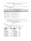
An example of a command line which changes the parameters of the channel device connected to channel 1is shown
in the following example. The example changes the baud rate to 4800 bps, parity to odd, CTS flow control and turns
echo off
ATC1B4800P1F1E0
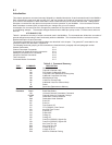
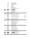
Table 5-1 presents a summary of all the commands used in the MultiMux. The commands are divided into a number of
general categories according to their functionality within the MultiMux. This functional division is carried on into the
detailed description of each command.
The access commands for the command modem are described in this chapter. The general AT commands for the
command modem are described in Appendix D.
The following functional grouping of the commands are listed with their paragraph title and paragraph number:
General Commands 5.2.1
Channel Parameter Commands 5.2.2
Composite Link Speed & Clocking commands 5.2.3
Additional Composite Link Commands 5.2.4
Voice/Fax Channel Commands 5.2.5
Test Commands 5.2.6
Command Modem Commands 5.2.7
Table 5-1. Command Summary
TYPE COMMAND DESCRIPTION
General H General Help
H1 Channel Parameter Help
H2 DIP-Switch Configuration Help
H3 Composite Link Speed and Clocking Help
H4 Additional Composite Link Help
H5 Miscellaneous Help
H6 Voice/Fax Channel Help
H7 Additional Voice/Fax Channel Help
Z Reset
&W Store New Parameters to Memory
Channel B0 Channel Off Command
Parameter Bxxx Baud Rate Select
C0 Universal Channel Parameters Command
C1-C32 Channel Select for Parameter Change
DC Destination Channel Selection
DN Destination Node Selection
E0 Echo Off
E1 Echo On
F0 Flow Control Off
F1 CTS (RS232C) Flow Control
F2 Xon/Xoff Flow Control
F3 Enq/Ack On
F4 EnqAck Off
F5 Pacing On
F6 Pacing Off
F7 Pass EIA (RS232C) Signals On
F8 Pass EIA (RS232C) Signals Off
F9 Xon Pass Thru On
F10 Xon Pass Thru Off
F11 Inverter DTR On
F12 Inverter DTR Off
F13 Xoff/First Character Pacing