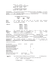
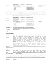
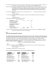
ATV(1/2)LIFXSL FXS w/Loop Connects a single
Start Line telephone/fax with a loop start line to the mux.
ATV(1/2)LIE&M(1-5) E&M Interface Connects to E&M trunk (D/W)(2-4)
side of a PBX.
(1-5) Selects E&M type 1-5.
(D/W) Selects E&M dial or wink
(2/4) Selects E&M 2 or 4-wire
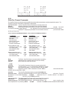
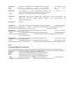
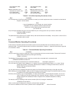
Voice/Fax Channel The Voice/Fax Remote Channel Interface command informs the Remote Interface local voice/fax
channel of how the remote channel may be configured. A word of caution here, this command does not V(1/2)RI
actually change the remote interface. You may have to contact the remote site for verification of its actual interface.
The V1RIFXS command says that the remote interface is set for an FXS
connection. If erratic voice/fax operation is noticed, the remote interface may be incorrectly set at the local MultiMux. The
Remote Channel Interface commands are as follows:
ATV(1/2)RIFXO FXO Interface Station side of PBX.
ATV(1/2)RIFXSG FXS w/Ground Single telephone/fax
Start Line with Ground Start.
ATV(1/2)RIFXSL FXS w/Loop Single telephone/fax
Start Line with Loop Start.
ATV(1/2)RIE&M(1-5) E&M Interface Connects to E&M trunk (D/W)(2-4)
side of a PBX.
(1-5) Selects E&M type 1-5.
(D/W) Selects E&M dial or wink
(2/4) Selects E&M 2 or 4-wire
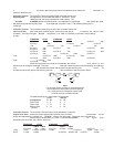
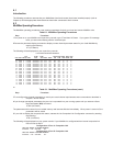
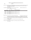
Voice/Fax Channel The Wink Timer command is used in the E&M interface to delay
Wink Timer the sending of address information from the remote MultiMux.
The wink timer range is from 100 to 350 milliseconds. The default
V(1/2)WT delay is 250 msec.
5.2.6
Test Commands
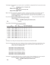
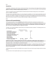
Memory There are two memory tests available on the MultiMux. The first
Test test (&T1) will alter the contents of the basic system memory,
which is automatically restored when power is turned on to the
&T1-2 system or when a reset command is executed. The second
memory test (&T2) alters the contents of the memory that stores
parameters. When this test is executed, a warning is given that
stored parameters will be destroyed. If the Memory Test 2 (&T2)
passes, the factory default parameters will be loaded into your
MultiMux.
When executing any of the memory tests, a complete cycle is
indicated by a message on the supervisory console and test
errors are indicated by appropriate messages.
Test Mode 3 Test Mode 3 tests the memory located on the voice/fax board (if installed) that is common to the voice/
fax and system boards.
&T3
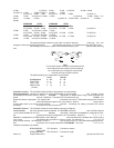
Test Mode 4 Test Mode 4 is the Local Loop test which checks the operation
of a local MultiMux. This test mode will cause data
&T4 entered on channel device keyboards to be echoed back to the devices monitor. When initiating this
test, downline loading must be disabled.
Test Mode 5 &T5 Test Mode 5 is the Remote Loop test which causes any data from the composite link to be
echoed through the DSU and back to the link. This command is used so that the local MultiMux can have data entered
on its channel devices echoed back to the same originating channel device monitor. When initiating this test, the
source and destination nodes on the local MultiMux must have the same values and the downline load feature disabled.
Test Mode 6 Not Used.


