


2.2
Configuration 1
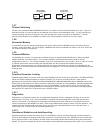
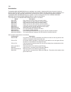
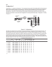
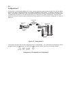
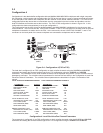
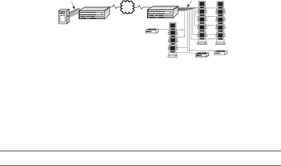
Configuration 1 is a data-only configuration. This configuration has two Multi-Tech MultiMux MMV1616C/56 which are
sixteen channel multiplexers with internal 56K bps composite link DSUs linking sites one and two over a Digital Data
Service (DDS) network provided by your telco facility. The local site has the MMV1616C/56 connected to a host
minicomputer. The remote site has fourteen terminals and two shared printers connected to the asynchronous
channels of the remote mux. At the remote site, the terminals are communicating with the remote mux on 19.2K bps
asynchronous channels, and the printers are configured for one setting above its cps rating. Configuration 1 is shown
in Figure 2-1.
Channel 9 Channel 10 Channel 11 Channel 12
Channel 13 Channel 14 Channel 15
Channel 16
Channel 1 Channel 2
Channel 3 Channel 4
Channel 5 Channel 6 Channel 7 Channel 8
Composite Link A Composite Link B
Command Modem
Voice/Fax Channel 1
Voice/Fax Channel 2
MultiMux 16
Data/Voice/Fax
Statistical Multiplexer
Systems
MultiTech
®
Local Site
Asynchronous
Channel
MultiMux MMV1616
PDN
Composite Link
Minicomputer
MultiMux MMV1616
Channel 9 Channel 10 Channel 11 Channel 12
Channel 13 Channel 14 Channel 15
Channel 16
Channel 1 Channel 2
Channel 3 Channel 4
Channel 5 Channel 6 Channel 7 Channel 8
Composite Link A Composite Link B
Command Modem
Voice/Fax Channel 1
Voice/Fax Channel 2
MultiMux 16
Data/Voice/Fax
Statistical Multiplexer
Systems
MultiTech
®
Asynchronous
Channel
Printer
Remote Site
Printer
Terminal
Terminal
Printer
Printer
Terminal
(Node 2)
(Node 1)
Digital Line
Figure 2-1. Configuration 1
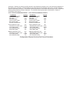
The local async channels can be configured to communicate with any of the async channels at the remote site. The
asynchronous channels of the local mux are configured with XON/XOFF software flow control enabled, so that the
channel buffers in the local mux do not lose data from the host. With flow control enabled at the local mux, the local
mux can tell the host when it feels that it's dynamic buffers are becoming full. For the same reasoning, pacing should
be enabled at the remote site printer channels to ensure that all data is received by the printers. Pacing allows the
printer to tell the remote mux not to send any more data until its buffers are cleared. Pacing may also be enabled at
the remote site terminal channels if it appears that data is being lost at the terminals. The first set of parameters in the
following examples are for the local mux and the second set are for the remote mux.
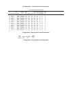
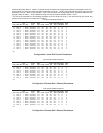
Local Channel Parameters/ Node # 01
STP FLOW ENQ/ PASS PASS DESTDEST LINK
CHN SPD WD BIT PAR CTRL ACK ECHO PACE EIA XON CHN NODE A/B
01 19200 8 1 NONE XON/XOFF OFF OFF OFF OFF OFF 01 02 A
02 19200 8 1 NONE XON/XOFF OFF OFF OFF OFF OFF 02 02 A
03 19200 8 1 NONE XON/XOFF OFF OFF OFF OFF OFF 03 02 A
04 19200 8 1 NONE XON/XOFF OFF OFF OFF OFF OFF 04 02 A
05 19200 8 1 NONE XON/XOFF OFF OFF OFF OFF OFF 05 02 A
06 19200 8 1 NONE XON/XOFF OFF OFF OFF OFF OFF 06 02 A
07 19200 8 1 NONE XON/XOFF OFF OFF OFF OFF OFF 07 02 A
08 19200 8 1 NONE XON/XOFF OFF OFF OFF OFF OFF 08 02 A
09 19200 8 1 NONE XON/XOFF OFF OFF OFF OFF OFF 09 02 A
10 19200 8 1 NONE XON/XOFF OFF OFF OFF OFF OFF 10 02 A
11 19200 8 1 NONE XON/XOFF OFF OFF OFF OFF OFF 11 02 A
12 19200 8 1 NONE XON/XOFF OFF OFF OFF OFF OFF 12 02 A
13 19200 8 1 NONE XON/XOFF OFF OFF OFF OFF OFF 13 02 A
14 19200 8 1 NONE XON/XOFF OFF OFF OFF OFF OFF 14 02 A
15 19200 8 1 NONE XON/XOFF OFF OFF OFF OFF OFF 15 02 A
16 19200 8 1 NONE XON/XOFF OFF OFF OFF OFF OFF 16 02 A
OK