


FCR The Flow Control Received (FCR) indicator lights when the remote MultiMux's buffers are full and the
local MultiMux has been told to stop sending data. The FCR indicator will only come On when
flow control is active. The FCR indicator lights for both internal DSU and an external link
device.
RD The Remote Down (RD) indicator lights when the local MultiMux cannot extablish communications
with the remote MultiMux. The RD indicator lights for both internal DSU and an external link
device.
TM The Test Mode (TM) indicator lights when the MultiMux is placed in test mode. Refer to Chapter 7 for test
mode operation.
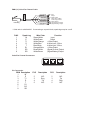
Table 3-1. LED Indicators (Continued)
Indicator Description
Command Modem
CD Indicates the local command modem has detected a carrier signal from a remote command modem.
RCV/XMT Indicates that the command modem is on-line by flashing with data activity between the two
command modems.
OH Indicates that the dial-up line for the command modem is off-hook.
Voice/Fax Channels
FXSThe Foreign Exchange Station (FXS) indicator lights when the designated channel is configured for FXS operation.
FXOThe Foreign Exchange Office (FXO) indicator lights when the designated channel is configured for FXO operation.
E&MThe Ear and Mouth (E&M) indicator lights when the designated channel is configured for E&M operation.
VCEThe voice (VCE) indicator lights when voice traffic is active on the designated channel.
FAXThe FAX indicator lights when fax traffic is active on the designated channel.
XMTThe transmit (XMT) indicator lights when voice or fax data is being transmitted on the designated channel.
RCVThe receive (RCV) indicator lights when voice or fax data is being received on the designated channel.
XSGThe transmit signal (XSG) LED lights when the FXS configured channel is off-hook, the FXO configured channel is
receiving a ring from the telco, or the M lead is active when the voice/fax channel is configured
for E&M opeation.
RSGThe receive signal (RSG) LED lights when the FXS configured channel is ringing or the E lead is active on the
E&M configured channel.
TM The test mode (TM) indicator lights when a test is being performed on a voice/fax channel.
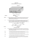
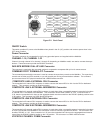
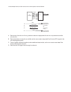
Back Panel
The cable connections for the MultiMux are made at the back panel. Refer to Chapter 4 for cabling installation
procedures. Refer to Appendix D for cabling diagrams. The MultiMux back panel is shown in Figure E-2.