


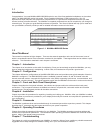

DATA
DATA
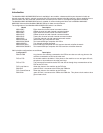
CHANNEL DEVICE
INITIATED PACING
Channel
Device
Channel
Device
Mux
Mux
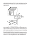
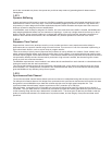
MUX INITIATED
FLOW CONTROL
Pacing stops the output
of data from the mux
Flow control stops the
input of data to the mux
1.5.7
Channel Switching
A feature of the MultiMux MMV1600/MMV3200 series is its ability to switch channels between mux units. That is, an
individual channel on a source node can be switched to any channel on its destination node. The only restriction on
channel switching is that the channel can only pass thoroughly six nodes on its way to its destination. Channel
switching adds flexibility to the MultiMux by allowing you to build networks matched to your user needs.
1.5.8
Parameter Memory
A nonvolatile memory for storing configurations and options means that the MultiMux remains configured until you
change it. Using this feature, you can configure a MultiMux and save the parameters to memory, turn it off, ship it and
use it without having to reconfigure it.
1.5.9
Command Modem
The MultiMux can connect to a dial-up phone network through an integral 2400/1200/300 bps V.22bis-compatible
modem called the command modem. The command modem is an asynchronous modem used for remote
configuration of the mux. The command modem is not to be confused with the link modem, which is either an internal
or external synchronous device handling the data transfers over the composite link between two muxes.
By using the command modem, you get the equivalent of a remote Command Port console. Your MultiMux can be
dialed into from a remote location for remote testing and configuration. The command modem will automatically answer
incoming calls.
1.5.10
Downline Parameter Loading
Operational parameters for both the local and remote MultiMux units can be set from one location. The MMV1600/3200
series can downline load parameters for the data channels, but not for the voice/fax channels. Data channel
parameters can be downline loaded to the MMV1600/MMV3200, MMH1600/MMH3200 and the MMH900 series units.
When power is first applied (or a Reset command is executed) to the local or remote MultiMux, operational parameters
are automatically sent over the composite link to the remote MultiMux. For this function to work, the 8-position DIP
switch SW1 on the local (sending) MultiMux must be set to the OPEN position and on the remote (receiving) MultiMux
the 8-position DIP switch SW1 must be set to the CLOSED position.
1.5.11
Diagnostics
Diagnostics in a multiplexer network are of considerable importance. When a multiplexer fails there is not just one
operator down, but many. That is why the MultiMux is equipped with several diagnostic modes that will test every
aspect of the network. The diagnostics include easy-to-execute tests for each channel, the composite link and for
various components of the MultiMux unit itself. There are ten different test modes to ensure error free operation. They
include Local and Remote Digital Loop tests, switch and LED tests, Nonvolatile Memory test, three other tests, a
Watch-dog Timer reset test, and the voice/fax loopback test.
1.5.12
Operational Statistics and Auto-Reporting
Operational statistics provides the activity report for the MultiMux network, and Auto-Reporting provides a means to
report on these statistics through the supervisory console on a set periodic time cycle. Statistics such as receive-block
errors pinpoint modem or line problems, and flow control time totals indicate channel devices being set at excessive
speeds. Two simple commands are all that is necessary to select statistical reporting and time cycle. If your command