


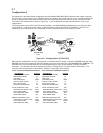


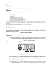

Sync Data Channel - Port B only
If Port B is being connected to a synchronous device, connect the back-to-back cable supplied with your
MultiMux to the COMPOSITE LINK B (RS232C/V.35) EXTERNAL MODEM/DSU connector on the
back panel of the MultiMux and the other end of the cable to the RS232C connector on the
synchronous device. Refer to the synchronous device documentaiton for this connection.
Async Channel
2 Route and connect your channel devices to the MultiMux back panel CHANNEL 1 - CHANNEL 16 for a
MultiMux MMV1616 or CHANNEL 1 - CHANNEL 32 for a MultiMux MMV3232 connectors using
RS232 cables.
Note
Any cables connected to the computer should be
shielded to reduce interference.
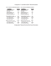
Table 4-1. Cabling Procedure
Step Procedure
Follow channel device guidelines regarding RS232 cable lengths and make sure that the pin assignment in
Appendices B and C of this manual are followed.
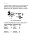
Voice/Fax Channels
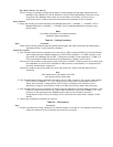
3 If the Voice/fax board is being connected to the trunk side of a PBX, connect the E&M (I-V) Voice/fax Channel
cable supplied with your MultiMux between the VOICE/FAX CHANNEL 1 or 2 E&M connector on the
back panel of the MultiMux and the PBX. Configuration 5 (E&M I-V) and configuration 7 (E&M I-V to
FXS) are examples of E&M connections and are described in Chapter 2 of this manual.
Connect the RJ45 connector of this cable to either VOICE/FAX CHANNEL 1 E&M connector on the back panel
of the MultiMux or to VOICE/FAX CHANNEL 2 E&M connector on the MultiMux. Pin assignments for
this cable are described in Appendix D.
Connect the spade lug end of this cable to the trunk side of the PBX. Refer to the PBX manual for this
connection.
Note
If the spade lugs are not needed on the PBX
end, they may be cut off the cable.
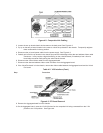
4 If the Voice/fax board is being connected to the station side of a PBX, connect an RJ11 phone cable between
the VOICE/FAX CHANNEL 1 or 2 FXO connector on the back panel of the MultiMux and to the
station side of the PBX. Configuration 4 (FXO to FXS) is a example of this connection and is
described in Chapter 2 of this manual. Refer to the PBX manual for the station side connection.
5 If the Voice/fax board is being connected to a station instrument (telephone, KTS-key telephone system, or fax
machine), connect one end of an RJ11 phone cable to either the VOICE/FAX CHANNEL 1 or 2 FXS
connector on the back panel of the MultiMux and the other end to the station instrument.
Configuration 6 (FXS to FXS) is an example of this connection and is described in Chapter 2 of this
manual.
6 Perform the configuration procedures in Table 4-3.
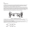
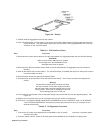
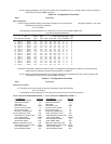
Table 4-2. V.35 Interface
Step Procedure
1 If either composite link is being connected to an external modem or DSU with a V.35 interface, loosen the four
quarter-turn-fasteners on the front panel and remove the front panel.