


2.5
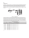
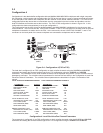
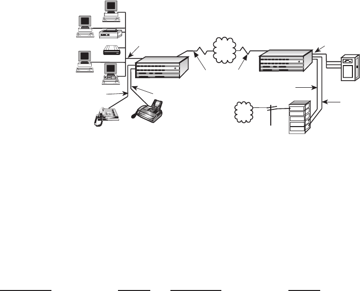
Configuration 4
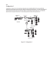
Configuration 4 is the data/voice/fax configuration with two MultiMux MMV1608C/56/V multiplexers with single composite
link connecting a minicomputer and the station side of a PBX at the local site to a group of remote terminals and printer
on the data part of the network and a telephone and fax machine on the remote voice/fax channels. This FXO to FXS
configuration allows the remote site to communicate over the composite link to the local site and be able to use the
local PBX facilities as if he/she were at the local site. The FXO to FXS configuration is shown in Figure 2-4. In this
configuration the data communications is set up per configuration 1.
This configuration has the MV2 Voice/Fax board installed in the MMV1608/56/V multiplexers for the voice over data
communications. The local site has the VOICE/FAX CHANNEL 1 and 2 FXO connectors on the back panel of the local
multiplexer connected to a station card in the PBX. At the remote site, the two VOICE/FAX CHANNEL 1 and 2 FXS
connectors on the back panel of the remote multiplexer are connected to a telephone and fax machine.
Voice/Fax
Channel 1
FXS
Multiplexer
Minicomputer
Asynchronous
Channel
Asynchronous
Channel
Multiplexer
Channel 9 Channel 10 Channel 11 Channel 12
Channel 13 Channel 14 Channel 15
Channel 16
Channel 1 Channel 2
Channel 3 Channel 4
Channel 5 Channel 6 Channel 7 Channel 8
Composite Link A Composite Link B
Command Modem
Voice/Fax Channel 1
Voice/Fax Channel 2
MultiMux 16
Data/Voice/Fax
Statistical Multiplexer
Systems
MultiTech
®
Composite Link
PC
Printer
Modem
PDN
2
3
1
4
5
6
7
9
8
Fax
Telephone
Terminal
Terminal
Terminal
Local Site
Remote Site
Voice/Fax
Channel 1 FXO
PBX
Trunk
Trunk
Station
Trunk
Station
PSTN
Voice/Fax Channel 2 FXS
Voice/Fax
Channel 2 FXO
(Node 1)
(Node 2)
Figure 2-4. Configuration 4 (FXO to FXS)
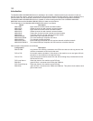
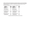
The local site is configured for an FXO configuration on both voice/fax channels using the V1LIFXO and V2LIFXO
commands and setting the Remote Interface type for an FXS configuration using the V1RIFXS and V2RIFXS
commands. The parameters for the local voice/fax channels can be displayed using the VL (List the voice/fax channel
parameters) command. The voice/fax channel parameters for the local site are shown in the Configuration 4 Local Site
Voice/Fax Channel Parameters. The voice/fax channel parameters are described in Chapter 5 Commands of this
manual.
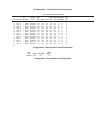
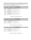
LOCAL VOICE/FAX PARAMETERS CHANNEL1 LOCAL VOICE/FAX PARAMTERS CHANNEL 2
PARAMETER STATUS PARAMETER STATUS
DESTINATION CHANNEL: 01 DESTINATION CHANNEL: 02
DESTINATION NODE: 02 DESTINATION NODE: 02
LINK A/B/D: A LINK A/B/D: A
DIGITIZING RATE: 16000 DIGITIZING RATE: 16000
OUTPUT LEVEL ATTEN.: 02 OUTPUT LEVEL ATTEN.: 02
INPUT LEVEL GAIN: 05 INPUT LEVEL GAIN: 05
SILENCE SUPPRESSION: 00 SILENCE SUPPRESSION: 00
LOCAL INTERFACE TYPE: FXO LOCAL INTERFACE TYPE: FXO
GROUND/LOOP START (FXS): N/A GROUND/LOOP START (FXS): N/A
2 OR 4 WIRE (E&M): 2 WIRE 2 OR 4 WIRE (E&M): 2 WIRE
DIALTONE/WINK (E&M): N/A DIALTONE/WINK (E&M): N/A
WINK TIMER (E&M) N/A WINK TIMER (E&M) N/A
REMOTE INTERFACE TYPE: FXS REMOTE INTERFACE TYPE: FXS
GROUND/LOOP START (FXS): LOOP GROUND/LOOP START (FXS): LOOP
2 OR 4 WIRE (E&M): 2 WIRE 2 OR 4 WIRE (E&M): 2 WIRE
DIALTONE/WINK (E&M): N/A DIALTONE/WINK (E&M): N/A
Configuration 4 Local Site Voice/Fax Channel Parameters
The remote site is configured for an FXS configuration on both voice/fax channels using the V1LIFXS and V2LIFXS
commands and setting the Remote Interface type for an FXO configuration using the V1RIFXO and V1RIFXO