


2.6
Configuration 5
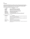
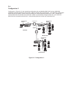
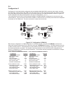
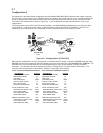
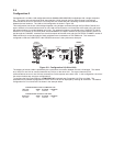
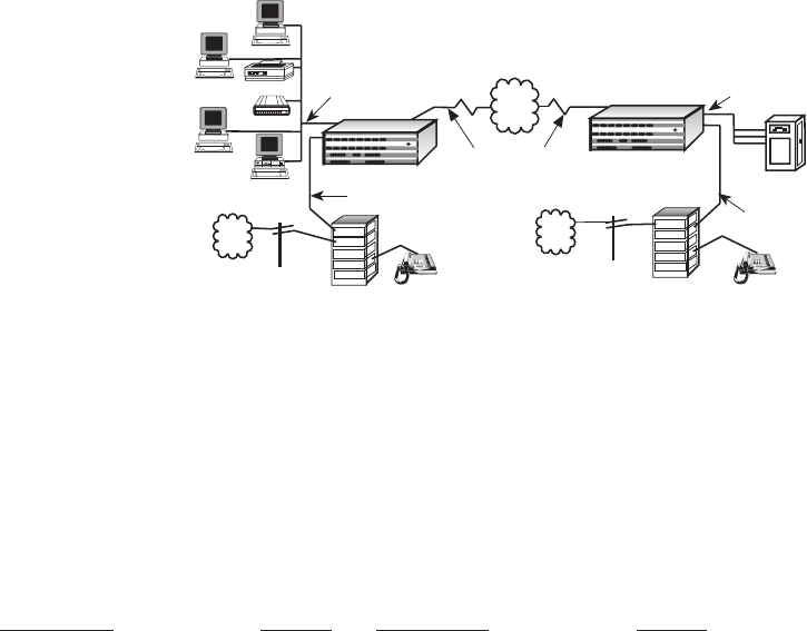
Configuration 5 is the data/voice/fax configuration with two MultiMux MMV1608C/56/V multiplexers with single composite
link connecting a minicomputer and a PBX trunk at the local site to a group of remote terminals and printer on the data
part of the network and a second PBX trunk on the voice/fax channels. The E&M configuration is shown in Figure 2-5.
In this configuration the data communications is set up per configurations 1, 2, or 3.
This configuration has the MV2 Voice/Fax board installed in the MMV1608/56/V multiplexers for the voice over data
communications. The local site has VOICE/FAX CHANNEL 1 E&M connector on the back panel of the local multiplexer
connected to a PBX E&M trunk. The same connection is made at the remote site.
Multiplexer
Minicomputer
Asynchronous
Channel
Asynchronous
Channel
Multiplexer
Channel 9 Channel 10 Channel 11 Channel 12
Channel 13 Channel 14 Channel 15
Channel 16
Channel 1 Channel 2
Channel 3 Channel 4
Channel 5 Channel 6 Channel 7 Channel 8
Composite Link A Composite Link B
Command Modem
Voice/Fax Channel 1
Voice/Fax Channel 2
MultiMux 16
Data/Voice/Fax
Statistical Multiplexer
Systems
MultiTech
®
Composite Link
PC
Printer
Modem
PDN
PSTN
Voice/Fax
Channel 1 E&M
Telephone
Terminal
Terminal
Terminal
Local Site
Remote Site
Voice/Fax
Channel 1 E&M
PBX
Trunk
Trunk
Station
Trunk
Station
PSTN
PBX
Trunk
Trunk
Station
Trunk
Station
Telephone
(Node 2)
(Node 1)
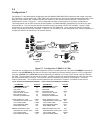
Figure 2-5. Configuration 5 (E&M I-V)
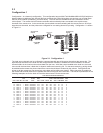
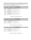
Both sites are configured for an E&M configuration on voice/fax channel 1 using the V1LIE&M1W4 command and
setting the Remote Interface type for the same thing using the V1RIE&M1W4 command. The E&M connections can be
to either voice/fax channel. The parameters for local voice/fax channels can be displayed using the VL (List the voice/
fax channel parameters) command. The voice/fax channel parameters for the local and remote configurations are
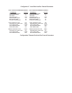
shown in Configuration 5 Voice/Fax Channel Parameters. The voice/fax channel parameters are described in Chapter
5 Commands of this manual.
LOCAL VOICE/FAX PARAMETERS CHANNEL1 LOCAL VOICE/FAX PARAMTERS CHANNEL 2
PARAMETER STATUS PARAMETER STATUS
DESTINATION CHANNEL: 01 DESTINATION CHANNEL: 02
DESTINATION NODE: 02 DESTINATION NODE: 02
LINK A/B/D: A LINK A/B/D: A
DIGITIZING RATE: 16000 DIGITIZING RATE: 16000
OUTPUT LEVEL ATTEN.: 14 OUTPUT LEVEL ATTEN.: 14
INPUT LEVEL GAIN: 05 INPUT LEVEL GAIN: 05
SILENCE SUPPRESSION: 00 SILENCE SUPPRESSION: 00
LOCAL INTERFACE TYPE: E&M 1 LOCAL INTERFACE TYPE: E&M 1
GROUND/LOOP START (FXS): N/A GROUND/LOOP START (FXS): N/A
2 OR 4 WIRE (E&M): 4 WIRE 2 OR 4 WIRE (E&M): 4 WIRE
DIALTONE/WINK (E&M): WINK DIALTONE/WINK (E&M): WINK
WINK TIMER (E&M) 100 WINK TIMER (E&M) 100
REMOTE INTERFACE TYPE: E&M 1 REMOTE INTERFACE TYPE: E&M 1
GROUND/LOOP START (FXS): N/A GROUND/LOOP START (FXS): N/A
2 OR 4 WIRE (E&M): 4 WIRE 2 OR 4 WIRE (E&M): 4 WIRE
DIALTONE/WINK (E&M): WINK DIALTONE/WINK (E&M): WINK