


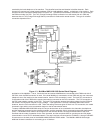
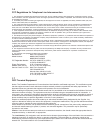
received by the local telephone or fax machine. The voice/fax board has two identical voice/fax channels. Each
channel can connect to a private branch exchange (PBX, a small telephone switch), a telephone or fax machine. Each
channel has three connectors labeled E&M, FXO and FXS. The E&M (Ear and Mouth) connection is for connecting to
the E&M trunk side of a PBX. The FXO (Foreign Exchange Office) connection is to the station side of a PBX and
assumes that an FXS (Foreign Exchange Station) connection is made at the remote location. The type of voice/fax
connection depends on the
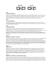
Figure 1-3. MultiMux MMV1600/3200 Series Block Diagram
application of the MultiMux. That is, if both the local and remote MultiMuxes are connected to the E&M trunk side of
the PBXs, then the E&M connection is used. If the local MultiMux is connected to a local PBX and only one instrument
(telephone set or fax machine) at the remote location, then the FXO connection is used. The local FXO connection is
to the station side of the PBX and the remote instrument is connected to the FXS connection. The FXO connection to
the PBX uses a station number on the PBX. The local FXO connection accepts the ringing voltage from the PBX and
the remote FXS connection outputs a ringing voltage. If the application is to have a dedicated instrument at both
locations, then the FXS connection is used. When the calling instrument goes off hook in a FXS connection, the called
instrument rings and the voice conversation begins or the fax transmission starts.
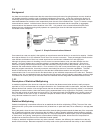
To setup a MultiMux MMV1600/3200 series, the async devices have to be connected to the channels, the telephone
and fax machines connected to the voice/fax channels, and the composite link(s) connected to the public data network
(PDN). The MultiMux then needs to be configured for the channel devices, the origin and destination of the voice
channels and the mode of operation for the voice channels, and the composite links for synchronous and full duplex
communication over a DDS or dedicated network. The async devices are connected to CHANNEL 1 through CHANNEL
8 connectors on the back panel of the MultiMux MMV1608 with RS232 cables. The MultiMux MMV1616 has eight
additional channel connectors for connecting up to 16 devices.